
What was the challenge or problem to solve?
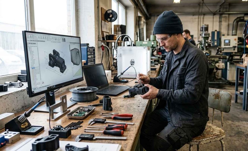
A company was developing a new device that had to integrate different functional elements inside it. Before approving a version, it needed to try new geometries and compare materials in order to then obtain physical samples with which to validate the real behavior of the product. The starting point was a preliminary model 3D-printed, useful for seeing the shape but insufficient for making decisions about material and manufacturing.
INFINITIA took part from the selection of materials through to the fine-tuning of a molding tool. The challenge was not only to choose the best combination of geometry and material, but to leave the client a tool with which to produce, on their own and manually, enough samples for their first batches.
3D-printed prototype: how far validation goes
The client had a preliminary version of one of the models, manufactured in rigid PLA by 3D printing. PLA is a plant-based thermoplastic very common in rapid prototyping because it allows parts to be obtained quickly and cheaply, but its rigidity and mechanical behavior do not reflect the performance the final product demands.
A prototype printed in a rigid material solves the validation of shape, dimensions and the fit of the internal elements, but it does not anticipate how a flexible part will respond in real use. Added to that limitation is the fact that a part obtained by depositing material layer by layer does not behave the same as a part cast in a mold, even if both share the same geometry. That first model served to visualize the product, not to decide which material it should be manufactured in nor to test geometry variants with different mechanical responses.
Separating what was already validated, the general shape, from what remained to be decided, the material and the fine geometry, made it possible to focus the project’s effort where it added the most value. That is why the work began by defining precisely what needed to be checked before manufacturing anything.
Translating the client’s need into clear technical criteria, that is, defining the product requirements and specifications, avoids repeating prototypes and guides both the choice of material and the subsequent design of the mold. In a device that integrates elements inside it, those criteria cover the shape, the dimensions, the intended use and the function each part must fulfill.
Material selection by hardness: how to narrow the options
The second front of the challenge was the selection of materials suitable for the samples. The device required exploring different degrees of hardness, understood as a material’s resistance to being penetrated or deformed, a property that directly conditions the feel, the flexibility and the function of the new product.
In polymers and elastomers, hardness is expressed through standardized scales and measured with a durometer, using Shore A for flexible materials and Shore D for the more rigid ones. Having a common scale makes it possible to describe the sought-after behavior with objective criteria, compare candidates with one another and prevent the decision from depending on subjective impressions.
The difficulty was not only in finding a material, but in narrowing down a set of options comparable to one another, with different hardness and suitable for the intended manufacturing process. A good fit between material and process reduces the risk of discarding valid geometries because of a manufacturing problem, and not a design one.
Selecting the material by hardness conditions the feel, the flexibility and the function of the product, so defining it before manufacturing reduces the number of iterations needed.

This approach follows the logic of material selection for industrial applications, which seeks the best balance between technical properties, in-service behavior and manufacturing feasibility, instead of reaching the definitive material by elimination after several failed attempts.
Manual casting of 20 to 60 samples: the tooling challenge
The most demanding challenge for INFINITIA came at the end of the path. Once the definitive geometry was chosen, the client needed to produce between 20 and 60 samples simultaneously, on their own premises and by manual casting, without series equipment or injection machinery.
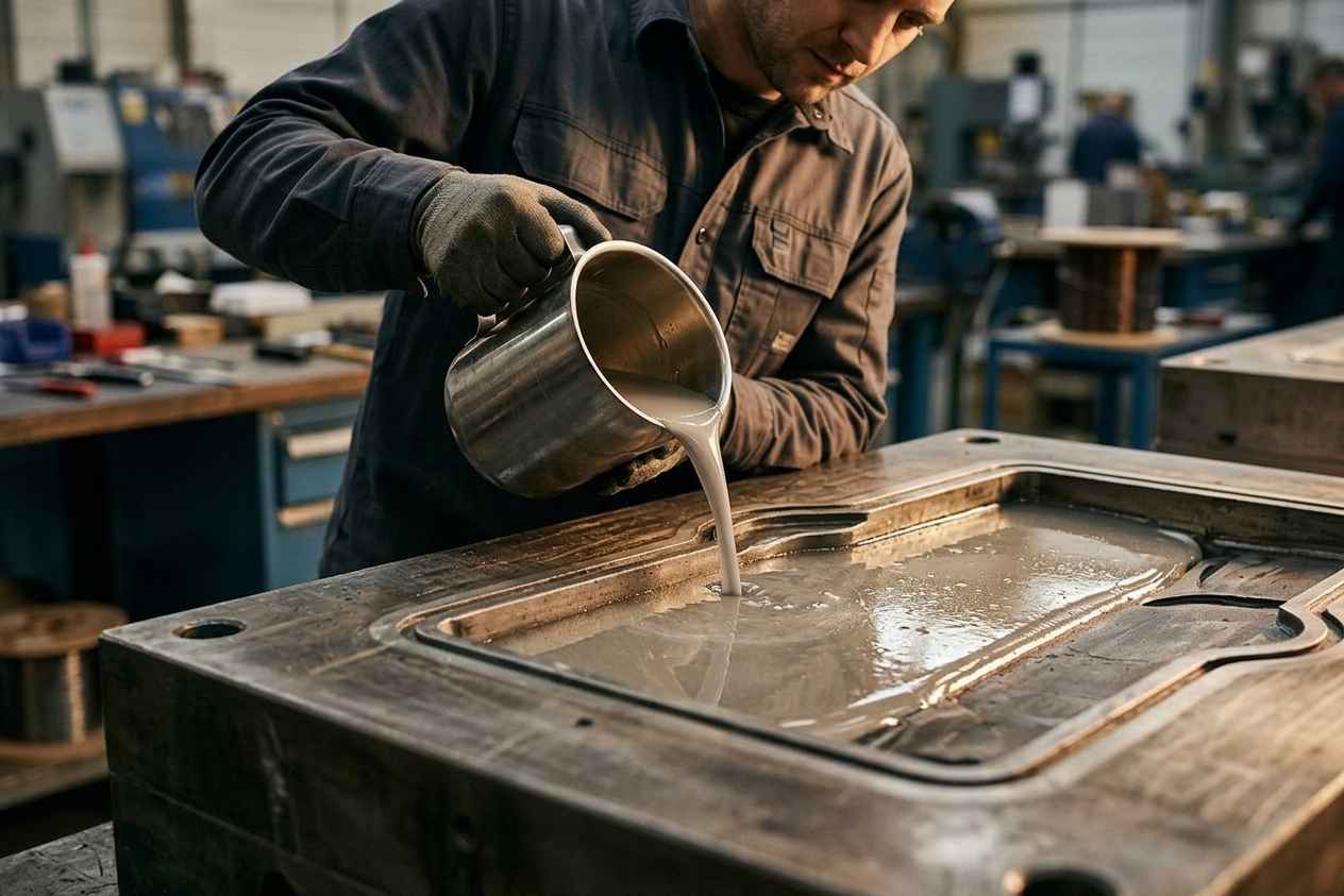
Manual casting, or manual pouring, consists of pouring a castable material into a mold and letting it copy the geometry of the part as it solidifies or cures, to then extract it from the tool. For that method to be viable in volume, the tool must be precise, repeatable and simple to handle by the client themselves, so that each sample comes out the same as the previous one without intermediate adjustments.
For a volume of between 20 and 60 units, manual casting is a coherent route, because it covers the need for enough physical samples for the first tests and the first batches without the cost or the lead times of an injection tool, reserved for much larger runs. The goal was for the client to gain productive autonomy at a scale proportional to their development stage.
Designing that molding tool was, therefore, the true core of the assignment: a tool that would transfer the validated geometry to dozens of reliable physical samples, conceived to produce the first batches without depending on a larger industrial investment and without requiring prior molding knowledge from the client.
How was it addressed, or what was the solution?
The Product Development team laid out a path in linked phases, in which each step prepared the next and reduced uncertainty before committing resources. First narrow down materials, then model and prototype and, only at the end, with the geometry already validated, develop and manufacture the definitive tool.
This order is deliberate. Bringing the material and the geometry to a solid point before investing in the mold avoids redoing work and concentrates the spend on the phase in which there are no longer open unknowns. INFINITIA kept technical criteria as the priority at all times, supporting every decision on data and not on assumptions.
Study and purchase of materials: three comparable options
The first task consisted of studying the most suitable available materials for the project and acquiring them. The team focused on two criteria: the possibility of testing different degrees of hardness and the ease of use of each material within the prototype-creation process.
That second criterion is decisive when the destination of the project is a manual casting mold, because the material must be able to be handled and poured outside an automated production environment. Compiling and comparing this information makes it possible to give the client a range of real alternatives, with their advantages and limitations, instead of imposing a single solution. On that basis, the client selected three materials with which to continue the development.
Presenting several comparable material options, instead of just one, lets the client decide with criteria and speeds up the validation of the geometry.
That the final decision rests with the client, with the technical information already organized and contrasted, is consistent with the role of external technical partner: it provides industrial criteria without replacing the knowledge the company has of its own product and its user.
Comparing candidates on measurable properties, and not by intuition, is precisely what material characterization provides, allowing the real behavior of each option to be known before manufacturing. The purchase of the materials closed this stage and ensured that the three alternatives were available and consistent throughout the whole project.
3D CAD modeling according to the client’s specifications
With the materials narrowed down, the team addressed the 3D CAD modeling based on the client’s specifications. Using professional computer-aided design software, and the information provided about shape, dimensions, use and function, the team generated the digital models of the different geometry variants.
The CAD model is the common reference for the whole project, because both the prototypes and, later, the mold itself come out of it. Any geometry adjustment is resolved in the digital model before consuming material, which makes iterations cheaper and maintains traceability between what is designed and what is manufactured.
Modeling while already thinking about the subsequent process avoids redoing work. A cycle of mechanical development that goes from CAD modeling to tooling design treats the part and its mold as parts of the same problem, and not as independent phases resolved separately.
In this case that continuity was especially relevant, since the geometry validated with the prototypes would be the one that later had to be reproduced in the tool, with the constraints of manual casting and the chosen material.
Physical prototypes in three materials to validate hardness
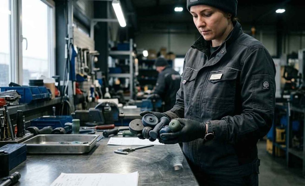
From the digital models, the team moved on to the creation of physical prototypes, manufacturing samples with each of the three materials selected by the client. Having real prototypes, and not just images on a screen, is what makes it possible to check both the geometry and the hardness in a tangible way.
Once manufactured, those samples were sent to the client so they could carry out the necessary tests in their own context of use. This exchange closes the loop between design and validation, because each prototype provides concrete information that helps converge toward the definitive geometry and material.
Working in parallel on three materials, and not sequentially, shortens the validation time and provides a direct comparison between alternatives under the same conditions of use. With equivalent samples in hand, the choice stops being a design hypothesis and comes to rest on how each option behaves when the device is actually used.
Using prototyping as a decision tool, and not as a presentation mock-up, is what makes it possible to reach the tooling phase with the unknowns cleared up: which geometry has to be reproduced and with which material to do it.
Molding tool: from the validated model to dozens of samples
With the geometry already selected, the team developed and manufactured the definitive molding tool. This tool transfers the validated geometry to a mold with which the client can manually produce, on their own premises, enough physical samples for the first production batches.
The design of the tool took into account the demands of manual casting: dimensional precision to reproduce the part faithfully, the capacity to obtain several samples in a single pour, repeatability so that the 20 to 60 units came out homogeneous and simplicity of handling so that the client themselves could operate it.
Orienting the design to those conditions responds to the logic of design for manufacturing, which adapts the part and its mold to the real production method. In a mold for manual casting, this translates into decisions about the parting line, the filling of the cavity or the extraction of the already-cured part, which are the ones that determine whether the process is viable by hand.
A well-designed molding tool turns a validated geometry into dozens of homogeneous samples producible by hand, without the need for an industrial run.
The result of the project was clear: the client obtained all the samples they needed, with a new geometry and a material different from that of the initial prototype, plus a tool of their own with which to keep manufacturing them without depending on third parties or on an industrial run.