
What was the challenge or problem to solve?
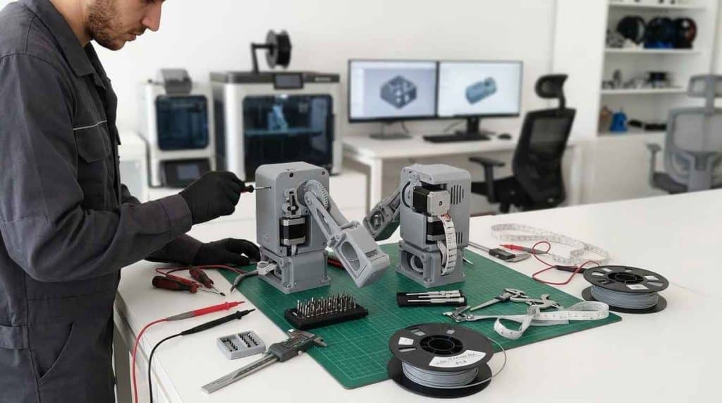
A functional physical prototype is a physical model that reproduces the real behaviour of a product and makes it possible to check that the idea behind it works before investing in its industrialisation. Many companies and industrial entrepreneurs reach this point with a solid idea and with graphic material that explains it at a conceptual level, but without the internal technical capacity to turn all of that into an object that can be touched, operated and shown.
That was the starting point of this product development project. The client had an idea at a conceptual level, set out in two versions (one electronic and one analogue), and needed physical models that showed their product in operation. The assignment consisted of covering the complete path that separates a drawn concept from a designed, manufactured, assembled and tested prototype.
Why a functional prototype and not graphic material?
The client had defined their product on the plane of ideas. They had graphic material that showed, at a conceptual level, what they wanted to achieve and how the device should behave, including the existence of two different configurations to solve the same function. What did not exist was any real part: no defined geometries, no resolved mechanisms, no assembly that could be put together.
The need, therefore, was not aesthetic or about communication, but technical. To move forward, the client needed functional physical models, that is, prototypes capable of executing the intended sequence of use and not merely of resembling the imagined product. That distinction marks the difference between a mock-up, which represents the form, and a prototype, which demonstrates the operation.
The reason that led the client to seek an external technical partner was very specific: they did not have the internal capacity to develop their idea to the level of detail that manufacturing demands. Between a concept and a manufacturable part there is a leap that includes specifications, mechanisms, tolerances, materials and processes, and that leap requires a dedicated engineering team.
Prototype for investors: from promise to demonstration
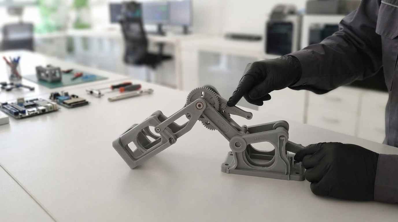
The second objective of the project was to show the idea to potential investors. A render or a diagram explain an intention, but they do not prove that the product works. A physical prototype, on the other hand, turns a promise into a demonstration: it is operated in front of the decision-maker and it is checked in real time that the idea holds up.
This difference conditions the scope of the work. A model intended for technical validation and external presentation must meet two conditions at once: work repeatably and be representative enough of the final product for the demonstration to be credible. Both requirements guide the design from the very first decision.
A prototype for investors only fulfils its function when it is operated: it demonstrates the real behaviour of the product, not the design intention.

In new-product projects, this phase also acts as a filter. Testing the prototype makes it possible to detect limitations before committing investment in tooling, moulds or production runs, which is where planning errors become expensive. The same questions that an industrial proof of concept resolves appear here: whether the idea is viable, whether the mechanism responds and whether the product does what is expected of it.
Mechanical development of two versions proposed by the client
The challenge taken on by the Product Development team was the development and manufacture of a functional prototype of the versions proposed by the client. The difficulty did not lie in a single critical component, but in the starting point: everything the concept did not specify had to be defined from scratch.
Mechanical development is the engineering discipline that transforms a functional need into completely defined parts and assemblies, with their geometry, their materials, their tolerances and their associated manufacturing process. It is, in practice, the bridge between the concept and the manufacturing reality, and it is exactly the stretch the client could not cover on their own. This is how it is addressed within our mechanical product development service.
Added to that demand was the coexistence of two versions, electronic and analogue, which had to solve the same function through different approaches. Working on both in parallel forces a common, coherent requirements definition to be maintained, so that the two configurations respond to the same criteria of use and can be compared with one another on a homogeneous basis.
How was it addressed, or what was the solution?
The solution was structured as an orderly development process, in which each phase resolved a specific question before enabling the next. This approach avoids the most common mistake in projects born from an idea: starting to model geometries without having first agreed on what the product must meet.
The project was addressed in linked phases: definition of specifications and ideation of concepts, mechanical development through 3D CAD design and, finally, manufacturing, assembly and testing.
How a product is defined before designing it
The project began with an initial and maturation study aimed at determining the specifications and requirements of the design. The specifications are the set of characteristics, functionalities and constraints that the product must meet, expressed in verifiable terms. To extract them, the team analysed all the available information: the different types of product proposed, the mechanisms involved and the existing products that solved similar needs, a state-of-the-art analysis that reveals which solutions exist and where there is real room for differentiation.
Documenting the specifications provides an advantage that is maintained throughout the development: it keeps present, in each iteration, the requirements that must be met and works as an acceptance criterion for each concept and, later, for the manufactured prototype. This work corresponds to the phase of defining product requirements and specifications.
With the specifications closed, an ideation process was carried out from which three different concepts emerged to tackle the project. Ideation consists of generating, in a structured way, several solutions to the same requirement and turning them into evaluable concepts. The method used was brainstorming, applied in a directed way on the requirements already extracted: proposing several lines of work instead of just one forces the design decisions to be made explicit and prevents the development from being conditioned by the first solution that appears, which is rarely the best.
Generating three product concepts and comparing them with their pros and cons turns a design decision into an informed decision by the client.
The three concepts were presented to the client, explaining the advantages and disadvantages of each, so that they could choose the one that best suited their needs. This decision point is deliberate: the client knows their market and their priorities, and the technical team provides the feasibility criterion. The full methodology is detailed in the product ideation and concepts service.
3D CAD design for the mechanical development of the concept
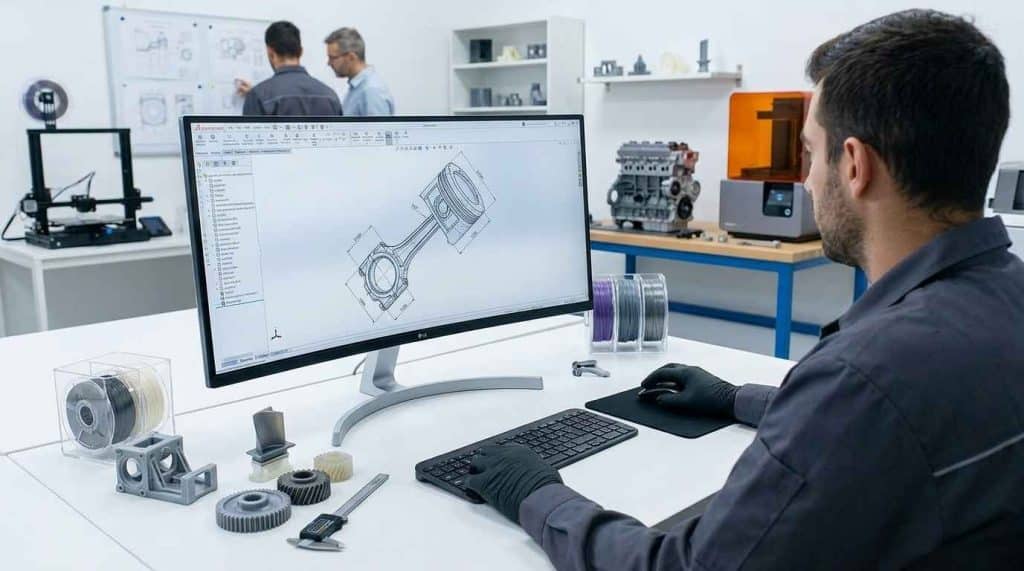
Once the concept was defined and selected, its mechanical development was carried out. Using professional CAD (computer-aided design) software, all the 3D models needed to manufacture the prototype were obtained, including the parts and the assemblies that had to be put together.
3D CAD design makes it possible to reach the level of detail that manufacturing demands: it defines exact geometries, fits between parts, clearances of the mechanisms and the assembly sequence. Working in a parametric environment adds a decisive advantage in prototyping projects, since, when necessary, changes are applied quickly and easily and propagate to the rest of the assembly. Since a prototype is conceived precisely to discover what was not known, that ability to iterate without redoing the model directly conditions the project’s timeline.
The digital model is also the handover point towards manufacturing. From the CAD come the files that feed the production process, which directly links 3D design and modelling using CAD with the next stage.
Additive manufacturing, assembly and testing of the functional prototype
With all the CAD models available, the manufacturing, assembly and testing of the prototype were carried out. All the parts were obtained through additive manufacturing. 3D printing produces complex geometries without tooling, allows each part to be manufactured individually and permits redesigning and reprinting a specific component without affecting the rest. For a prototype of unique parts and several foreseeable iterations, it is the shortest path between the digital model and the assembled set.
Additive manufacturing turns a CAD model into real parts without tooling, which allows a prototype to be iterated part by part.
Once manufactured and assembled, the prototype was tested to guarantee its operation. The product’s sequence of use was then documented and explained to the client, so that the operation was clear and the result matched what was expected. The client thus obtained the mechanical development of their design and the manufactured prototype, and was able to show their idea to potential investors.