
What was the challenge or problem to solve?
Product redesign aimed at registering a utility model consists of taking an idea to a level of technical definition sufficient to manufacture a prototype and generate the graphic documentation required by the utility model registration. Without that intermediate step, the proposal remains in the realm of intuition: it cannot be verified physically or delimited with the precision that an industrial property title requires.
Behind this commission was a company with a clear improvement idea and the will to protect it, but without the technical means to take it from concept to object. The client wanted to register a utility model based on an approach that would allow different parts to be assembled without dismantling the mechanical elements of the assembly and, at the same time, to vary one of the product’s parameters, in this case the diameter of one of the parts. The functional advantage was clear to the client, but neither the defined geometry nor the physical support that would allow it to be demonstrated existed yet.
Utility model: what technical documentation its registration requires
A utility model is an industrial property title that protects inventions consisting of giving an object a configuration, structure or constitution from which an appreciable advantage for its use or manufacture results. In Spain it is regulated by Patents Law 24/2015, processed before the Spanish Patent and Trademark Office (OEPM) and grants ten years of non-extendable protection from the filing date of the application.
The difference between an idea and a registrable utility model is one of level of specificity. The file rests on a technical description and on claims that delimit exactly what is protected, and those claims need to be supported by drawings that represent the object’s configuration unambiguously. That graphic material is not an aesthetic accompaniment, but the documentary proof that the invention exists as a defined object and not as an intention.
Choosing the right protection route also depends on what you want to protect. The utility model protects inventions of a lower inventive level than the patent and lasts ten years, compared to the twenty of the latter. It also differs from industrial design in that it protects the practical utility derived from a configuration, and not the aesthetic appearance of the product. In this project, what added value was strictly functional, the possibility of interchanging parts without dismantling the mechanical elements and of varying the diameter of one of them, which places the protection within the scope of the utility model.
Translating that functional advantage into concrete geometry, with its interfaces, its clearances and its assembly sequence resolved, was the precondition for any procedure.
Registering a utility model does not protect an idea, but a defined configuration: without concrete geometry there is no claim to sustain.

Product redesign without an in-house technical development team
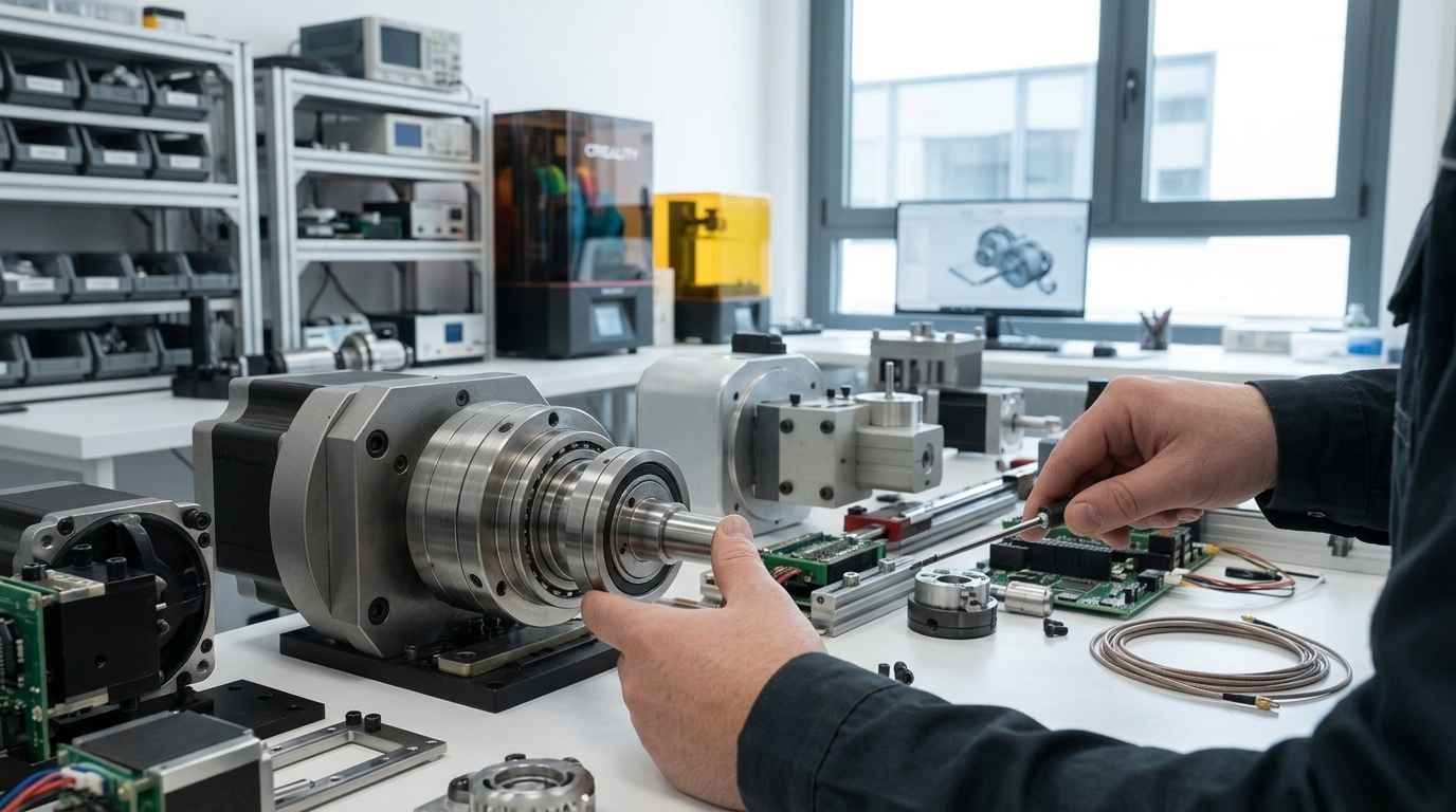
The reason that led the client to seek external support was a very specific capability limitation: it had neither technical development capacity nor the means to generate the graphic material needed for the utility registration. It had the application criterion, that is, it knew what the product should do and why that improvement had value, but not the engineering capacity to materialise it.
This situation is common in companies and industrial promoters with a deep knowledge of their application and without their own engineering structure. Turning to an external technical partner provides access to that capacity without taking on the burden of a design department, and doing so at the point in the project when it is really needed.
The commission also had an implicit constraint: it was not about inventing a product from scratch, but about redesigning an existing one by incorporating the new functionality. That requires respecting already-proven features while modifying the assembly architecture, a balance that conditions all subsequent decisions.
Functional prototype: how far the idea has to be developed
The challenge taken on by INFINITIA’s Product Development team was to develop the idea to a point sufficient to manufacture a prototype that would allow the client to validate its approach. The difficulty was not in drawing, but in deciding where to place that point: too early and the prototype demonstrates nothing, too late and effort is invested in details that validation may disprove.
A functional prototype is a physical materialisation of the design that reproduces the behaviour to be tested, even if it does not yet incorporate the materials or processes of series manufacturing. Its function is to answer a specific question with physical evidence, and in industrial prototyping that question must be posed before manufacturing the part, because it determines what level of detail is essential and which is dispensable.
Here the question was twofold. On the one hand, whether the new mechanism really allowed parts to be assembled and changed without dismantling the assembly and by varying the diameter. On the other, whether that modification of the architecture did not degrade the product’s behaviour: the redesign had to maintain a level of mechanical resistance comparable to that of the original product, something that can only be affirmed after testing it.
How was it addressed or what was the solution?
The project was approached as a structured product development process organised into four chained phases: initial study and specifications, conceptualisation, design development in CAD and manufacturing with prototype validation. Each phase closed one uncertainty before opening the next, so that no detail decision was made on an unverified hypothesis.
The team worked as the client’s external technical partner, not as the executor of a closed commission. This means that the client took part in the relevant decision points, especially in the choice of concept, and that the result was oriented from the outset towards two simultaneous deliverables: a prototype with which to validate the idea and the graphic material with which to process the registration of the utility model.
Design specifications from an existing physical model
The first task was an initial study of the product in which an existing physical model was selected that would serve as the basis for the redesign and for the subsequent testing of the new product. Analysing that current product made it possible to determine the specifications and requirements that the design to be developed had to meet.
Design specifications are the set of characteristics, functionalities and restrictions that the product must satisfy, expressed in a verifiable way. The definition of product requirements and specifications fulfils a double function here: it serves as the basis for the following phases and ensures that all necessary points are covered, without omissions that appear when the design is already advanced and correcting them is expensive.
Starting from an existing physical model also provides a measurable reference. The original product is not only the functional comparison point, but the pattern against which the redesign’s performance will later be contrasted, starting with its mechanical behaviour. Without that physical reference, the subsequent validation would have lacked a term of comparison.
Design specifications set the acceptance criterion before the first line is drawn: without them, every subsequent decision is made without reference.
Product conceptualisation: three lines of work compared
The second phase was conceptualisation. Through a brainstorming process and with the design specifications always present, three different lines of work were proposed to tackle the development of the new design, each accompanied by its pros and cons.
Working with several concepts in parallel is not an accumulation exercise, but a decision method. Putting the advantages and disadvantages of each alternative on the table allows approaches to be compared with explicit criteria and the most suitable to be chosen according to what the client prioritises, not what is most comfortable to design. In the product design and innovation service, this ideation phase is precisely the one that translates a need into several possible technical solutions.
In this project, that comparison had an added value: the choice of concept was made by the client. On receiving three technically evaluated lines of work, it could select the one that best suited its needs and what it wanted to protect with the utility model, with knowledge of the implications of each option.
3D CAD design of the chosen concept to manufacture the prototype
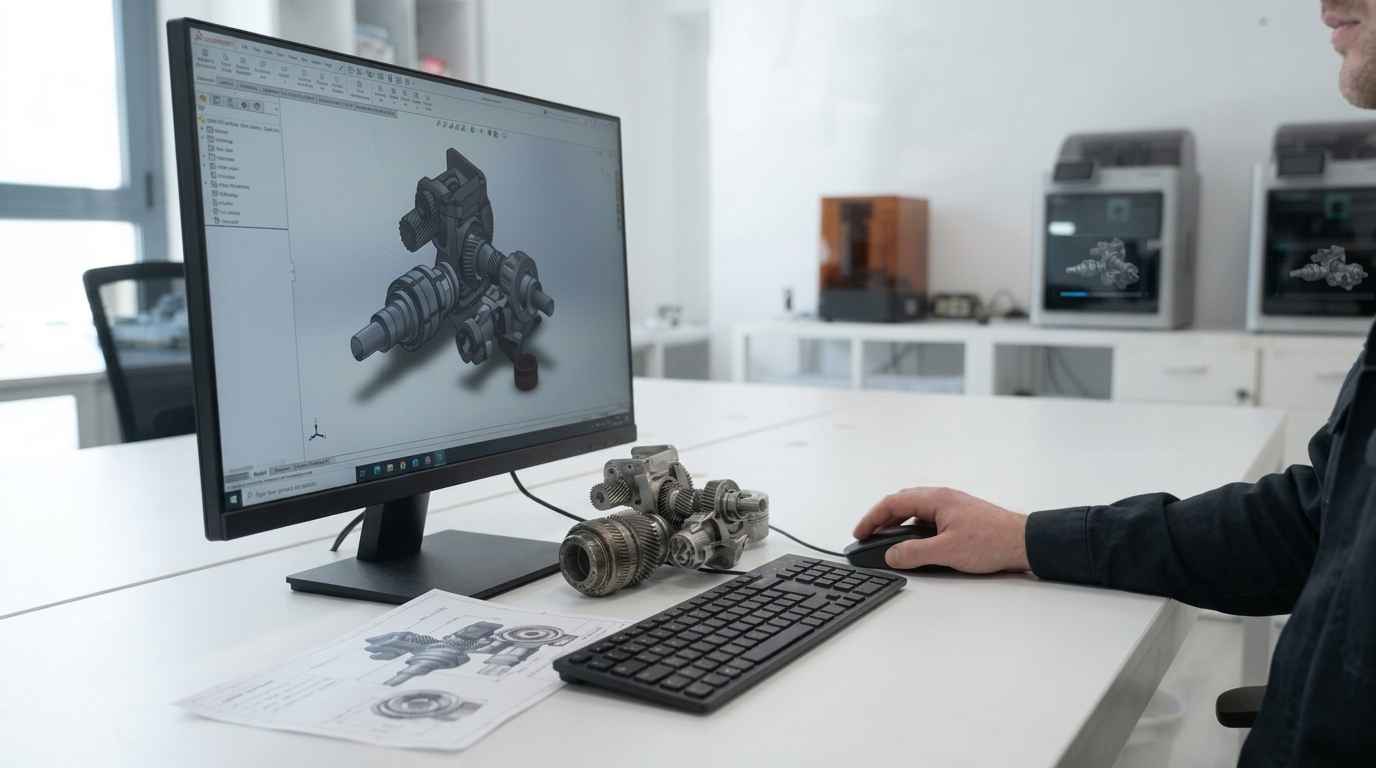
With the concept selected, the design for the future manufacture of the prototype was developed. Using professional CAD software, all the necessary 3D models were generated, defining the complete geometry of each part and of the assembly.
3D CAD design is the tool that turns a concept into a complete, manufacturable geometric definition. In mechanical product development, that definition is not limited to the shape: it incorporates the interfaces between parts, the fits and the tolerances that determine whether the assembly works in practice.
The use of this software made it possible to reach the level of detail sufficient for the manufacture of prototypes, which was exactly the project’s objective. In addition, and this is decisive in a development that must still be validated, modelling allows changes to be made quickly: when testing returns information, the design can be adjusted without redoing the work from the beginning.
The 3D models also fulfilled the second mission of the commission. The same geometric definition that allows manufacturing is the one that allows generating the coherent and precise graphic material that the registration of the utility model requires, so that both deliverables come from a single technical source and cannot contradict each other.
Prototype manufacturing and validation of mechanical resistance
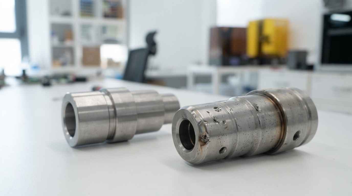
The last phase consisted of the manufacture of prototypes of the developed design and its validation and testing. Two prototypes were manufactured with different purposes: one intended for testing and technical validation, and another so that the client had a physical support with which to convey its idea.
That duplication responds to two uses that should not be mixed. The test prototype is subjected to tests and may be damaged or modified during them, while the communication prototype must remain intact to be shown to third parties, whether partners, manufacturers or interlocutors in the registration process. Separating both functions prevents validation from compromising the specimen intended to explain the idea.
Carrying out tests made it possible to verify the design’s suitability in terms of mechanical resistance with respect to the original product. This verification is the one that closes the project’s circle: it confirms that the new assembly architecture, the one that allows parts to be interchanged without dismantling the mechanical elements and varying the diameter, is not achieved at the expense of the structural behaviour of the starting product.
A functional prototype turns validation into a physical check: it allows the mechanical resistance of a redesign to be contrasted against the original product before committing investments.
The result was the one foreseen in the initial approach: the client obtained a prototype that allowed it to validate its idea and the graphic material needed to carry out the registration of the utility model, starting from a proposal that had no prior technical development.