
What was the challenge or problem to solve?
Reverse engineering of a product, or digitisation of parts, is the technical process that reconstructs its geometry, its dimensions and its manufacturing documentation from the physical parts, when no digital models or original drawings exist. In this project, an industrial company had a product made up of several parts and needed to digitise it to obtain the files with which to manufacture it. The starting point was physical units, with no digital support to work from.
The need did not arise from a failure in service, but from a process decision: the company wanted to introduce improvements in the automation of the assembly of the product. That industrial objective, and not digitisation in itself, is what gave the project its purpose and conditioned both its scope and its deadline. Recovering the geometry of each part is, in fact, a task of product development and, specifically, of mechanical development, because the shape and dimensions of each component are what later condition the tooling and the assembly system that will be designed around them.
Assembly automation that demands prior digital geometry
Automating assembly means replacing manual operations with systems that position, orient and join parts repeatably. To design those systems (grippers, clamping tooling, positioners or assembly stations) it is essential to know exactly the shape, the dimensions and the bearing surfaces of each component that will be handled.
That information existed in the product, but only in physical form. Without a digital model it is not possible to design tooling that fits the real part or to check accesses and collisions before manufacturing anything. Any decision made on an estimated geometry is later passed on to redesign costs and shop-floor adjustments, which is exactly what an automation project seeks to avoid.
Hence the client’s specific need: to digitise a series of parts of which it only had physical units. The digitisation of parts was not the final objective, but the prior technical condition for advancing with the automation project.
Digitising parts with no original drawings or documentation
Working with a product without digital files is a common situation in industry. It happens with old developments, with assemblies inherited from a previous supplier or with products that were never fully documented. The component works and is assembled, but the company has no control over its technical definition.
In these cases two distinct deliverables are missing. The 3D CAD model is the editable three-dimensional file that reproduces the geometry and on which the associated tooling can be simulated, modified or designed. The 2D drawing is the dimensioned document that translates that geometry into dimensions, tolerances and acceptance criteria so that a manufacturer can produce it. One does not replace the other: they describe the same part for two different uses.
Recovering both documents is what gives the company back the ability to decide about its own product, from modifying it to commissioning its manufacture with criteria.
Without an editable 3D CAD model or a dimensioned 2D drawing, a company can manufacture its product, but it cannot intervene on it or change supplier with technical criteria.
Reverse engineering on a tight deadline, the challenge for the technical team
The challenge of this project was to obtain all the documents needed for manufacturing in a very short period of time. It was not about digitising an isolated part, but a set of several, and about delivering for each one both the three-dimensional model and its dimensioned drawing.
The difficulty of a short deadline in reverse engineering has a structural cause: the process is chained. The capture of the geometry conditions the modelling, and the modelling conditions the drawings. An error in the first stage is not detected until the end, when time has already been invested in the following ones. Compressing deadlines therefore requires verifying each stage before advancing, not accelerating them all at once.
For this reason the company turned to INFINITIA. The Product Development team took on the project applying reverse engineering with an industrial approach, aimed at making the resulting files directly usable in manufacturing and not merely an approximate representation of the part.
How was it addressed or what was the solution?
The project was structured into three chained tasks, each with a verifiable deliverable: 3D scanning of the physical parts, generation of the 3D CAD models from the captured geometry, and preparation of the dimensioned 2D drawings. This order runs the reverse path to that of a conventional development, from the finished object to its technical definition.
The work was carried out by INFINITIA’s specialised team, combining digitisation means and parametric modelling software, always according to the final use the client would give to each document. Verifying each task before moving on to the next is what made it possible to hold the deadline without carrying errors from one stage to another.
3D scanning of parts to capture the real geometry
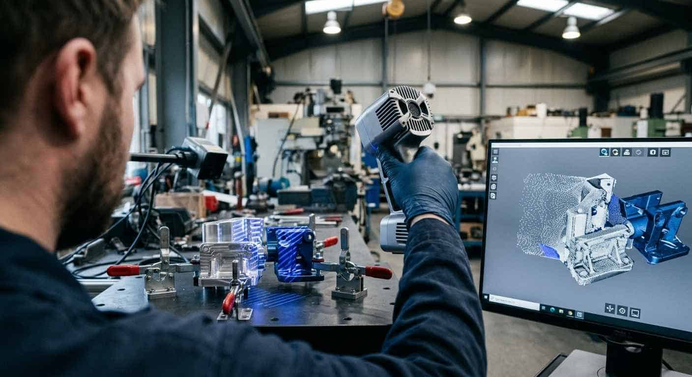
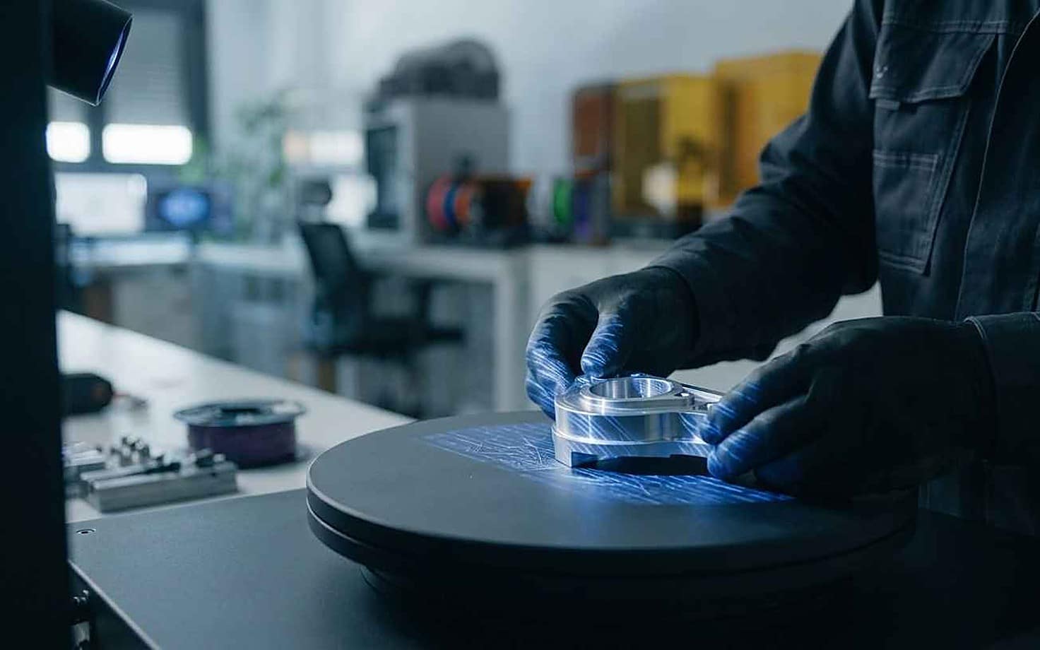
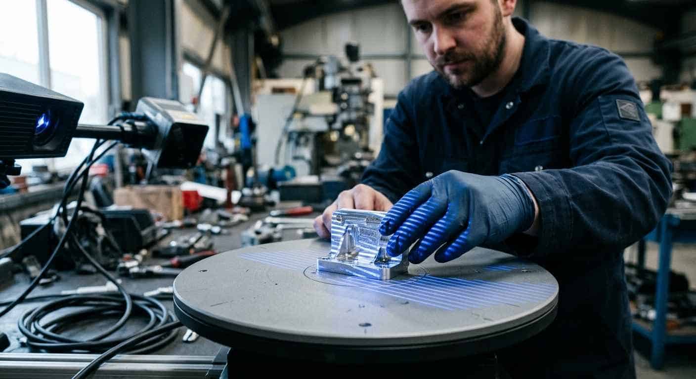
The first task was to carry out the reverse engineering to obtain the geometries from the physical parts. The samples received were prepared for their 3D scanning, a metrology technique that reconstructs an object three-dimensionally by optically capturing millions of points of its surface. 3D scanning and the digitisation of parts record details that a manual measurement with a caliper hardly captures, such as curves or free-form surfaces.
The result of this stage is a point cloud, a set of three-dimensional coordinates with the complete information of the geometry. It is not yet a model usable in design: it is the raw data, faithful to the real part, on which the geometry is later built.
The scanning was performed with a maximum deviation of ±25 μm (0.025 mm), determined by the limitations of the 3D scanning equipment. That value defines the margin of uncertainty with which each surface is known and, therefore, the precision required of everything built from there, something especially relevant on the bearing and gripping surfaces on which the automated system will work.
From the point cloud to the parametric 3D CAD model
The second task was to generate the 3D CAD models from the geometry obtained. The point cloud generated in the scanning was used as the basis for drawing the part parametrically in the CAD software, obtaining the geometry closest to the real part through 3D design and modelling with CAD.
The difference between a mesh and a parametric model is decisive. A mesh represents the part but does not allow it to be modified with criteria: it does not distinguish a plane from a cylinder nor does it know the relationships between elements. A parametric model is built from geometric operations and constraints, so that each dimension can be edited and the whole is recalculated coherently.
It is what later allows a dimension to be adjusted, a positioning reference to be added or the part to be adapted to a new process, tasks proper to mechanical development that would be unfeasible on a non-editable mesh.
A model obtained by parametric modelling not only reproduces the part: it allows it to be modified, and that is the difference between digitising and recovering technical control of the product.
Dimensioned 2D drawings to manufacture the replica on a short deadline
The third task was to generate the 2D drawings from the 3D models, dimensioning the measurements of each part. It is the stage that translates the digital geometry into a language that any workshop can interpret and verify. One might wonder why a drawing is still necessary if the 3D model already exists, and the answer is that they answer different questions: the model describes the shape, while the drawing establishes which dimensions are critical, with what margin they must be met and how it will be checked that the part is acceptable.
A dimensioned 2D drawing does not repeat what the 3D model already says: it sets which dimensions are critical, with what tolerance and how it will be verified that the manufactured part is valid.
With these drawings, the client obtained in a short time all the 3D models and 2D drawings of the digitised parts. With that complete documentation it was able to continue with its initial objective, improving the automation of the product’s assembly, now on a verified geometric basis and not on estimates.
The generation of the drawings also brings a strategic consequence: it makes it possible to request the manufacturing of the parts from a manufacturer of its choice, without depending on whoever produced them originally. Documenting an existing product through reverse engineering thus stops being an exercise in copying and becomes a recovery of the product’s technical definition.