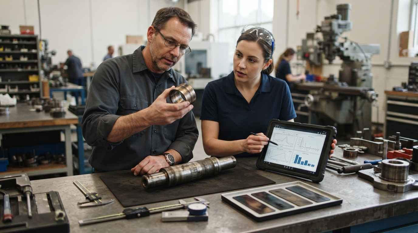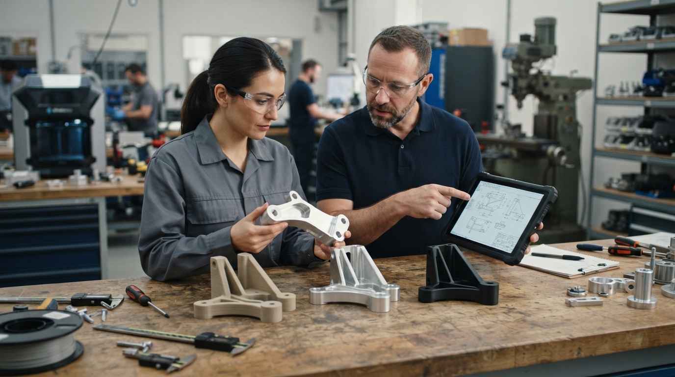

FEM simulation is enough when you are comparing design variants and sizing a part in the linear-elastic regime, with a well-characterised isotropic material and loads you actually know. You must test when the behaviour turns nonlinear (plasticity, large deformation, contact), when fatigue and life drive the design, when the material is anisotropic or a composite, when there are welded or adhesive joints, when the real load spectrum is uncertain, and whenever the part is safety-critical. And you always test at least once to validate the model itself.
That boundary is where a lot of engineering budgets are won or lost. Push everything onto a simulation and you ship a part that fails in a regime the model never described. Test everything and you burn weeks of prototype iteration you could have screened out numerically in an afternoon. Getting the split right is a product development decision, and within it a mechanical development one: which questions a finite element model can answer on its own, and which ones only a physical specimen under load can settle.
MECHANICAL DEVELOPMENT
Do you need to decide between FEM simulation and physical testing? Discover our mechanical development service

What structural analysis solves and what FEM simulation adds
Structural analysis is the discipline of predicting how a component responds to mechanical loads: the stresses that build up inside it, how much it deforms, whether it stays stable, and how it vibrates. For a simple bar, a bolt or a beam, closed-form equations answer those questions directly. Real parts have fillets, ribs, holes, variable thickness and combined loads that no textbook formula covers, and that is exactly where the finite element method earns its place.
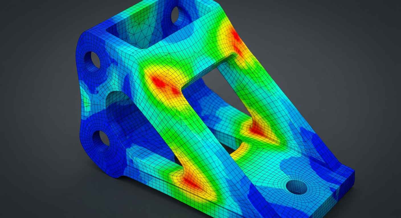
The finite element method breaks a continuous geometry into thousands or millions of small elements (the mesh), applies the material behaviour and the loads to each one, and solves the resulting system of equations for the whole part at once. From that solution you read the stress field, the strain distribution, the natural vibration modes and the buckling loads. A FEM simulation turns a CAD body into a map of where the part is highly loaded, where it has margin to spare, and where a redesign would actually change the outcome, and it does so while the design is still cheap to change, long before a prototype exists.
How the finite element method builds a stress field
Finite element analysis rests on three inputs that fully determine the result: the mesh, the boundary conditions and the loads. The mesh is the discretisation of the geometry into elements, and its refinement controls how faithfully sharp stress gradients around holes and fillets are captured. The boundary conditions describe how the part is held (fixed faces, supports, symmetry planes), and the loads describe what pushes on it (forces, pressures, thermal fields, imposed displacements).
Every one of those inputs is an assumption about reality, and the output inherits their quality. A clean mesh fed with a wrong constraint or an optimistic load produces a confident, precise, wrong answer, and it does so with the same colourful plots a correct model returns, which is what makes the error so easy to miss. Boundary conditions are by far the most common source of that error: a fixed support modelled as perfectly rigid, when the real part sits on a joint that flexes, overstates the stiffness of the assembly and moves the peak-stress location. That is why the restraint assumptions should always be checked against how the part is actually mounted, not against whatever is easiest to mesh. That work usually starts from the same geometry you build in 3D design and modeling using CAD, so the model and the drawing stay consistent as the design evolves.
What FEM simulation predicts beyond a hand calculation
Finite element analysis predicts quantities that hand calculations cannot reach on a real geometry: the peak stress concentration at a fillet radius, the full deflected shape under a combined load, the first natural frequencies and mode shapes, and the critical load at which a thin wall buckles. Comparing those numbers against the material strength, or against a target stiffness, is what lets you size wall thickness, place ribs and choose between two geometries before anything is machined. Each analysis type answers a different question, and choosing the wrong one is a subtle way to get a precise answer to a question that was never the relevant one.
A finite element model does not tell you whether a part is safe; it tells you how the part responds to the assumptions you fed it. The engineering value comes from choosing those assumptions well and knowing which ones a test still has to confirm.
When simulation is enough
Simulation is enough whenever the physics stays inside the region the model describes well and the inputs are known with confidence. In practice that means a linear-elastic regime (stresses below yield, small deformations), an isotropic material whose stiffness and strength you have characterised, a geometry and a set of loads you actually know, and a question that is comparative rather than absolute. Under those conditions a FEM simulation is fast, repeatable and cheap enough to run dozens of times.
The strongest use of finite element analysis is screening. Ranking rib layouts by peak stress, checking that a bracket clears its stiffness target, or confirming that a redesign lowers a known stress concentration are decisions the model settles on its own. You are not asking the software for the exact life of the part; you are asking which candidate is better, and relative comparisons between similar models are far more robust than any single absolute number.
Comparing design variants in the linear-elastic regime
Variant comparison is where simulation replaces prototype iteration most safely. When two designs share the same material, the same load case and the same boundary conditions, the differences in their stress and stiffness results are dominated by geometry, and that is precisely what you changed. You can move a rib, enlarge a radius or thin a wall and read the effect immediately, cutting the number of physical prototypes down to the final one or two candidates worth building for product manufacturing, where every late change multiplies its cost. That robustness has a firm limit: it only holds while the two variants share material, load and boundary conditions. As soon as more than one thing changes at a time, the differences can no longer be attributed to geometry and the comparison loses its value, so changing one factor per iteration is what keeps the decision criterion clean.
Feeding the model with measured material properties
A simulation is only as trustworthy as the material data behind it, and in the linear-elastic regime the governing inputs are the elastic modulus, Poisson’s ratio and the yield strength. When those come from a tensile test on the actual alloy rather than a generic datasheet, the stress field lands where the real part will load. ISO 6892 defines the tensile test that provides those elastic and yield properties, and characterising the specific batch through mechanical properties testing removes one of the largest sources of model error before you even mesh the part. When the properties come from a generic datasheet, the model inherits an uncertainty that no mesh refinement can correct, and the discrepancy only surfaces at the final test, when redesign is most expensive. Measuring first is almost always cheaper than discovering the gap last.
The table below sets out where the boundary between simulation and testing falls, criterion by criterion.
| Criterion | When simulation is enough | When you must test |
|---|---|---|
| Material behaviour | Linear-elastic, stresses below yield | Plasticity, large deformation, hyperelastic or rate-dependent response |
| Material type | Isotropic and well characterised | Anisotropic, composite or heterogeneous material |
| Loads | Static, known magnitude and direction | Uncertain real load spectrum, impact or variable service loads |
| Failure mode | Static overload against yield or ultimate strength | Fatigue, crack growth, creep or long-term degradation |
| Joints and contact | Continuous body, bonded interfaces | Welded or adhesive joints, frictional contact, preloaded fasteners |
| Purpose | Comparing variants, sizing, screening before prototyping | Certifying a safety-critical part or validating the model |
TELL US ABOUT YOUR CASE
Do you have a design to validate by simulation or test? Send us your case and we will propose the right combination of FEM and testing
When you must test, no exceptions
You must test whenever the design is governed by physics the model represents poorly, or by inputs you cannot pin down on a screen. Each of the situations below moves the deciding evidence out of the solver and onto a specimen, because the failure mechanism, the material response or the real loading is either nonlinear, uncertain or too consequential to accept on simulation alone. The more safety-critical the function, the less negotiable that rule becomes.
Nonlinearities, fatigue and uncertain loads that simulation cannot close
Nonlinear behaviour is the first hard boundary. Once a part yields, deforms largely, or its response depends on frictional contact and separating surfaces, the linear-elastic assumptions break and the accuracy of the result depends heavily on modelling choices that need experimental anchoring. Fatigue is the second: predicting how many cycles a part survives depends on the material’s fatigue behaviour and on the real load spectrum, and both carry scatter that a deterministic model does not capture. ISO 1099 covers axial-force fatigue testing on metals, the kind of data that turns a fatigue estimate into a defensible life. INFINITIA has redesigned cracked components on exactly this basis in a fatigue analysis and redesign of cracked components project, where the mechanism was cyclic, not static overload.
Anisotropic materials, joints and safety-critical parts
Composites and other anisotropic materials break the isotropy the simplest models assume: stiffness and strength depend on direction and on the layup, and a wrong ply orientation invalidates the whole result. In a laminate the same model can predict global stiffness well and still be completely wrong about the instant and the mode of failure, because rupture starts in one ply and progresses in a way a mean-stress criterion does not capture. Telling apart predicting stiffness from predicting fracture is decisive: the first is often within reach of the calculation, the second almost always demands a test. Welded and adhesive joints add heat-affected zones, residual stresses and bond behaviour that no idealised geometry reproduces, which is why joint failures so often surprise a model that looked clean. And when the part is safety-critical, the cost of a wrong assumption is measured in more than rework, so a physical test becomes non-negotiable regardless of how good the simulation looks. A field failure such as this hinge failure analysis shows how the real fracture surface tells a story the pre-production model never anticipated, and failure analysis is how that gap between predicted and actual behaviour gets closed.
The dangerous simulations are not the ones that fail obviously; they are the confident ones run outside their valid regime, where a clean stress plot hides plasticity, a fatigue mechanism or a joint the model never represented.
How to correlate simulation and testing
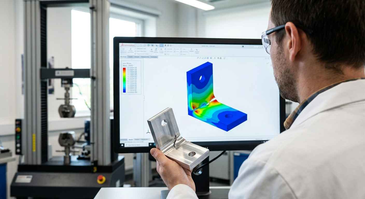
Correlating simulation and testing means treating the physical test as the ground truth and using it to earn confidence in the model, in a structured loop rather than a one-off check. The recognised framework for this is verification and validation (V&V): verification asks whether you are solving the equations correctly, validation asks whether you are solving the correct equations for the real part. A finite element analysis you trust for decisions has passed both, and the second one is impossible without test data.
Verification and validation as the backbone of a trusted model
Verification comes first and is internal to the simulation. Mesh convergence is its central act: you refine the mesh until the result of interest stops changing, which proves the number you are reading is a property of the physics and not an artefact of a coarse discretisation. Validation then compares the converged model against measured reality, checking that predicted deflections, strains or natural frequencies match what an instrumented specimen actually does. Only a model that has been both verified and validated deserves to drive a design decision on its own, because a model can be numerically impeccable and still represent the wrong part. That is the real payoff of the loop: once a model is validated against a well-instrumented test, you can sweep dozens of load cases, temperatures or geometric variants with the confidence that the baseline behaviour is anchored in a physical measurement, which would be unthinkable if every scenario needed its own specimen.
Calibrating the model with measured test data
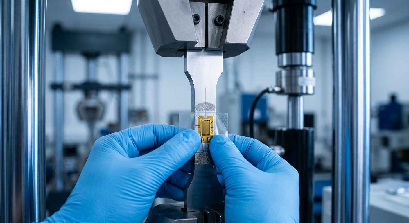
Calibration is where the two worlds meet. You feed the model measured properties (elastic modulus, yield, and where relevant fatigue and post-yield behaviour), run the equivalent load case, and compare against strains or displacements recorded on a real specimen. Where they disagree, the test is right and the model is adjusted, whether the gap comes from a boundary condition that is stiffer than reality or a material input taken from a datasheet instead of the batch. Establishing that baseline often draws on testing of metallic materials and alloys, and the same reasoning about how a material actually breaks runs through the distinction between brittle and ductile fracture, which a stress plot alone will never tell you apart.
Simulate to decide, test to trust
The productive way to use a FEM simulation is as the fast, cheap instrument that narrows the design space, not as the final word on whether a part is safe. Inside the linear-elastic regime, with a characterised isotropic material and loads you know, finite element analysis lets you compare variants, size sections and screen out weak candidates before cutting metal. Outside it (plasticity, fatigue, contact, anisotropy, joints, uncertain loads and safety-critical parts) a physical test is the evidence that counts, and even inside it one validation test is what turns a model into something you can defend. Simulate to decide between options; test to trust the one you chose.
If you are staring at a stress plot and cannot tell whether it settles the question or only postpones it, send us your geometry, your material data and the load case you are worried about, and get back a clear read on what the model already proves and which physical tests would close the remaining risk.
Frequently asked questions about FEM simulation
What is FEM simulation?
FEM simulation is a structural analysis method that divides a component’s geometry into many small elements (the mesh) and solves for how it responds to loads, predicting stresses, strains, vibration modes and buckling. It lets you evaluate a real part with fillets, holes and combined loads that no closed-form formula covers, which is why finite element analysis has become the default tool for sizing and comparing mechanical designs.
When is simulation enough and when must you test?
Simulation is enough when the part stays in the linear-elastic regime, the material is isotropic and well characterised, the loads are known, and the question is comparative (which variant is better, does it meet a stiffness target). You must test when there are nonlinearities, fatigue, contact, anisotropic or composite materials, welded or adhesive joints, uncertain real loads or safety-critical functions, and you always run at least one test to validate the model.
Does FEM simulation replace testing?
No. FEM simulation reduces how much physical testing you need by screening designs numerically, but it does not replace it, because the model’s accuracy depends on assumptions that only a test can confirm. The reliable approach uses simulation to decide between options and testing to validate the final design, especially for fatigue, joints, composites and any safety-critical part.
What data does a reliable FEM model need?
A reliable FEM model needs measured material properties (elastic modulus, Poisson’s ratio and yield strength for linear analysis, plus fatigue and post-yield data where they govern), a geometry consistent with the manufactured part, realistic boundary conditions, and a load case that reflects real service. Properties taken from a tensile test on the actual alloy, rather than a generic datasheet, remove one of the largest sources of error.
How do you validate a finite element model?
You validate a finite element model through verification and validation: verify it by refining the mesh until the result of interest stops changing (mesh convergence), then validate it by comparing predicted deflections, strains or natural frequencies against measurements from an instrumented specimen. Where they disagree, the test is treated as ground truth and the model is calibrated until it matches reality within an acceptable margin.