
Automotive prototyping validates, before you commit to hard tooling and series production, that a part performs its function, holds its dimensions, survives its service loads and can be manufactured at rate with stable quality. Each phase interrogates a different hypothesis, moving from technical feasibility to proven process capability.
Skipping a validation is rarely visible on the prototype bench; it surfaces months later as a warranty return, a line stoppage or a PPAP rejection. That is why the discipline matters more than the hardware itself. Before you refine a single part, it helps to see where prototyping sits inside product development, and to keep the transactional decision, procuring a build, on the prototyping service page rather than in the engineering rationale here.
The value of a structured prototyping route is that it forces each hypothesis to be tested against the right evidence, in the right order. A part that works in your hands has proven a design hypothesis; it has said nothing yet about whether the injection tool can produce ten thousand of it a week within tolerance. Conflating those two questions is the single most expensive mistake in the jump to series.
PROTOTYPING
Do you need prototypes to validate an automotive part before manufacturing? Discover our prototyping service

What each prototyping phase validates before production
Each prototyping phase answers a distinct question, so the evidence it produces is only valid for that question. Proof of concept confirms technical feasibility, the functional prototype confirms design behaviour, and the pre-series build confirms that the production process itself is capable. Treating them as interchangeable is where programmes lose time and money.
Proof of concept: validating the technical hypothesis
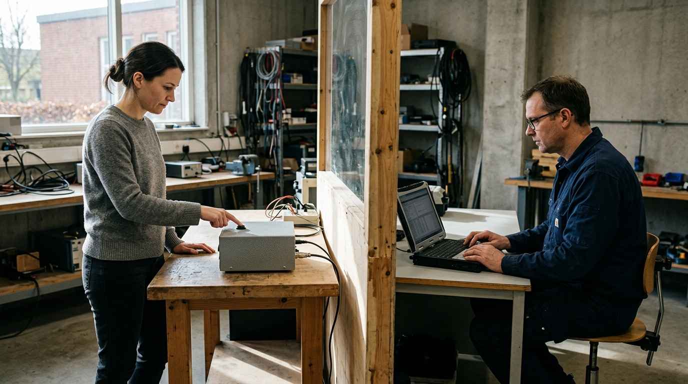
A proof of concept validates whether the core technical idea can work at all, isolating the one variable that carries the most risk. It is deliberately narrow: a kinematic principle, a sealing concept, a thermal path, a sensor integration. You are not yet asking whether the part is manufacturable or durable, only whether the physics holds.
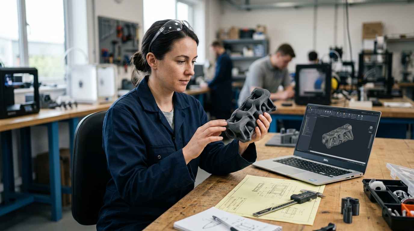
In automotive work this stage often uses additive methods and instrumented rigs to get an answer fast. A proof of concept built with 3D printing lets you interrogate geometry and fit within days, provided you remember that the printed material is a stand-in, not the series polymer. The risk if you skip this phase is committing design effort, and later tooling budget, to a concept that was never physically sound.
The functional prototype and its limits
A functional prototype validates design hypotheses under representative conditions, but it does not validate process hypotheses. It tells you the geometry, the interfaces and the intended behaviour are correct; it says nothing about whether the series process can reproduce that part consistently. This distinction governs how much weight you can put on the results.
A prototype machined from billet or printed in a high-grade resin can pass a functional test while hiding every problem the injection tool will later introduce: weld lines, fibre orientation, sink marks, shrinkage. The sibling discussion of what a functional prototype does and does not validate sets out that boundary in detail. Human factors and interface behaviour also live here, as in the user validation and design of a new device, where the prototype confirmed the interaction concept before industrialisation began.
A part you can hold and operate has proven a design hypothesis. It has proven nothing about whether the production process can make that part ten thousand times within tolerance, which is a separate question with separate evidence.
Types of prototype validation in automotive
Prototype validation splits into functional, dimensional, materials, durability and process families, and each family answers a failure question the others cannot. In automotive programmes these threads are planned together in a Design Verification Plan and Report (DVP&R), which maps every requirement to the test that proves it. Coverage matters more than test count.
Functional and dimensional validation with GD&T
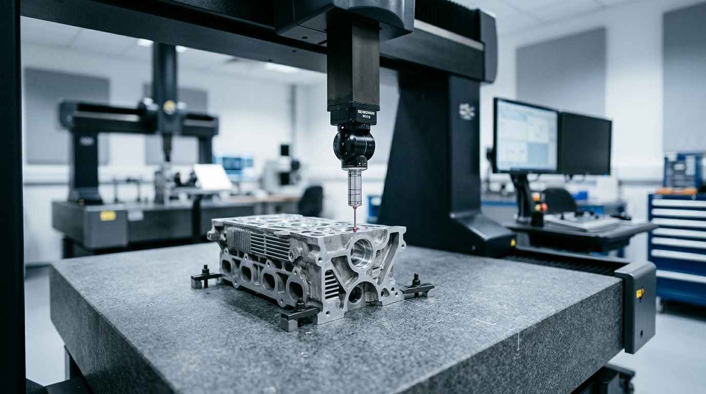
Functional validation confirms the part does what the specification demands, while dimensional validation confirms it stays within the geometric tolerances that make it assemble and seal. Geometric dimensioning and tolerancing (GD&T) turns fit intent into measurable datums, position and profile controls, so a CMM report either passes or fails against unambiguous criteria.
Dimensional work at prototype stage is where you discover whether the tolerances you drew are the tolerances the process can hold. A datum scheme that looks clean on the model can become uncontrollable once the part is clamped, moulded and cooled. Catching that on twenty pre-series parts is cheap; catching it after tool validation is not.
Materials and durability validation with DVP&R
Materials and durability validation confirms the part survives its service life, and each test type is chosen to provoke a specific failure mode rather than to accumulate hours. A representative durability plan maps loads to mechanisms so that a pass actually means something.
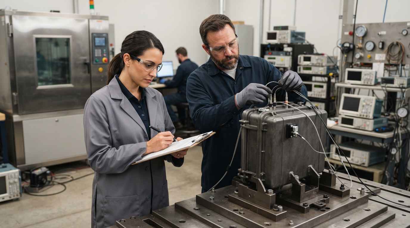
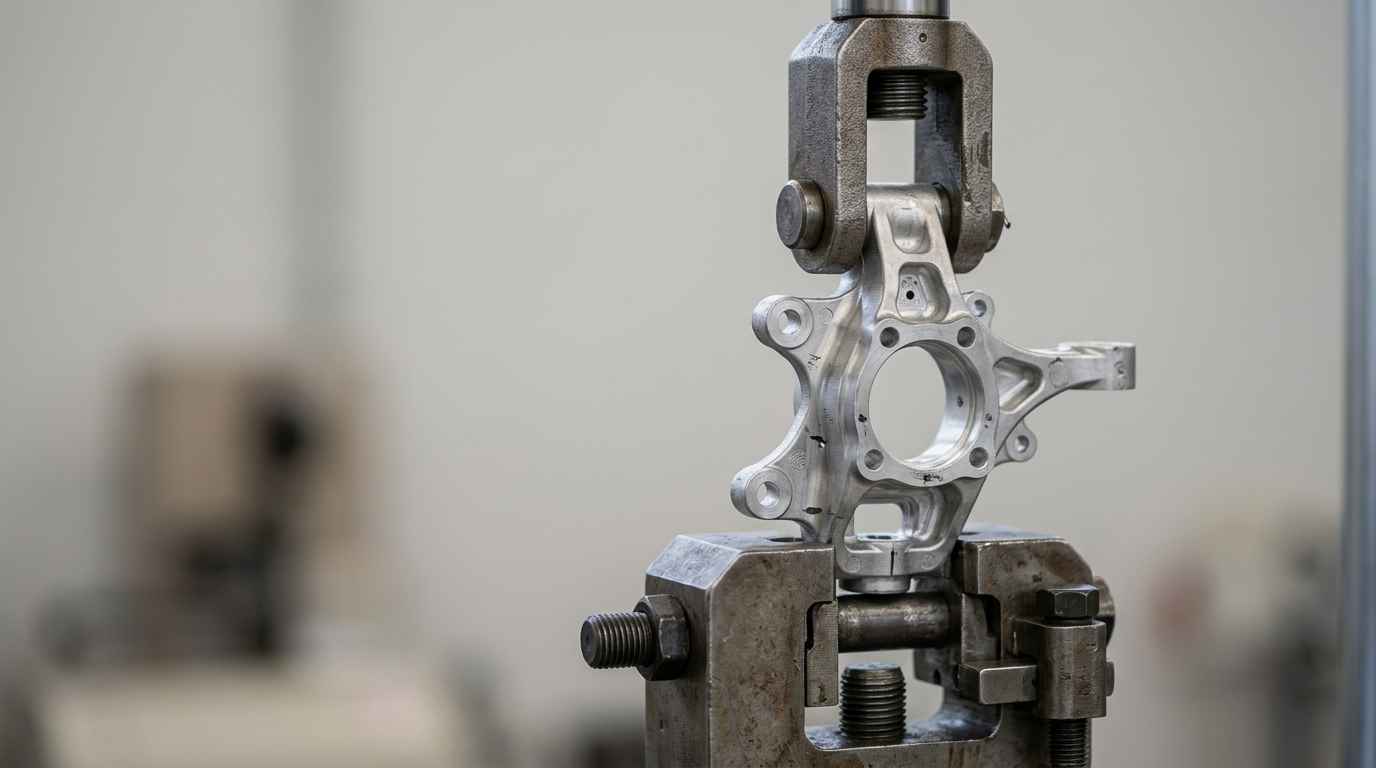
Fatigue testing applies cyclic mechanical load to interrogate crack initiation and propagation, the mechanism behind most structural durability failures. Random vibration and sine-sweep testing excite resonances and fastener loosening, exposing connector fretting and fatigue at welds and solder joints. Thermal shock drives the failure modes born of mismatched coefficients of thermal expansion, delamination, seal cracking and joint rupture. Climatic and ageing cycling, damp heat and thermal cycling, reveals polymer embrittlement, adhesion loss, corrosion and slow dimensional drift. Choosing the polymer and grade that will actually survive those cycles is a characterisation task; technology selection and testing is where that decision gets evidence instead of assumption.
| Phase | What it validates | What it does not validate yet | Typical technique or test | Risk if skipped |
|---|---|---|---|---|
| Proof of concept | Technical feasibility of the core principle | Manufacturability, durability, tolerances | Additive builds, instrumented bench rigs | Design and tooling budget spent on an unsound concept |
| Functional prototype | Design behaviour, fit, interfaces, function | Process capability and series-material behaviour | Machined or printed parts, functional and durability rigs, CMM | Weld lines, shrinkage and sink marks discovered after tooling |
| Pre-series and process validation | Production process capability at rate | Field durability beyond the validation window | PPAP, run@rate, Cp/Cpk, Gage R&R | PPAP rejection, line stoppages, warranty exposure |
Process validation before series production
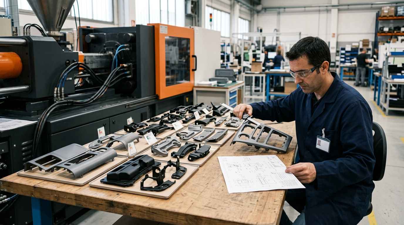
Process validation confirms that the production process, on production tooling and at production cadence, makes conforming parts repeatably, not that a single golden sample can be made. This is the phase most often underestimated, because a beautiful first-off article says nothing about the hundredth or the ten-thousandth. Automotive programmes formalise it through APQP and PPAP.
APQP, PPAP and run@rate validation
APQP is the advanced product quality planning framework that sequences a programme from concept to launch, and PPAP is the production part approval package that proves the process is ready. Under the IATF 16949 quality system, PPAP bundles the evidence, dimensional results, material certificates, capability studies and the DVP&R, into a submission your customer approves before series release.
Run@rate is the test that ties it together: you run the actual tool, on the actual line, at the actual takt time, and confirm the process holds capacity and quality simultaneously. A part that is dimensionally perfect at slow, supervised speed can drift the moment the line runs at rate, so validating at rate is non-negotiable. Skipping it converts a launch into a series of firefights.
Process capability and measurement systems: Cp, Cpk and MSA
Process capability quantifies how well a process fits inside its tolerance, with Cp describing potential spread and Cpk describing spread plus centring against the nearest limit. A capable, centred process shows Cp and Cpk close together and comfortably above the customer threshold; a gap between them signals a process running off-centre even if its spread is acceptable.
Before you trust any of those numbers, you have to measure the measurement. Measurement systems analysis (MSA), typically a Gage R&R study, quantifies how much of the observed variation comes from the gauge and the operator rather than the parts. If gauge variation eats a large share of your tolerance, your capability figures are fiction, and you may be scrapping good parts while passing bad ones. Measuring the measurement system first is what makes every downstream decision defensible.
Validating at rate is the difference between a controlled launch and a firefight. A process that makes one perfect part proves feasibility; a process that makes ten thousand within tolerance at takt time proves it is ready for series.
TELL US ABOUT YOUR CASE
Do you have an automotive design to validate with prototypes? Send us your case and we will propose a prototyping and testing plan
Design for manufacturing and industrialisation
Design for manufacturing is the discipline of shaping a part so the chosen process can make it repeatably, at cost and within tolerance, rather than fighting the geometry on every cycle. In automotive volumes, a design that ignores process physics turns every shift into a scrap-rate problem. Industrialisation is where design intent meets what the process can actually deliver.
DFM criteria that decide manufacturability
Manufacturability is decided by a handful of concrete geometric choices, each tied to how the process fills, cools and releases the part. For injection moulding, draft angles of around one degree per side let the part release cleanly, uniform wall thickness prevents the sink marks and warpage that follow uneven cooling, and generous radii instead of sharp internal corners both ease mould filling and remove stress concentrations. Parting-line placement decides where flash and witness marks land, and whether they fall on a functional or cosmetic surface.
These are the criteria that separate a part that industrialises smoothly from one that never stabilises. Applying design for manufacturing at prototype stage, before the tool is cut, is far cheaper than reworking steel. The product redesign to reduce cost and enable industrialisation shows what changes when manufacturability is treated as a design input rather than a downstream constraint.
Achievable tolerances by process
Achievable tolerance is a property of the process, not a wish written on the drawing, and specifying tighter than the process allows guarantees scrap. Injection moulding typically holds tolerances in the range of tenths of a millimetre, constrained by shrinkage, cavity-to-cavity variation and cooling, while machining reaches hundredths of a millimetre because material is removed from a stable blank. A GD&T callout that assumes machining precision on a moulded feature is a rejection waiting to happen.
The practical consequence is that you set tolerances against the process you will actually use in series, and you reserve tight callouts for the few features that truly need them. Over-specifying every dimension inflates cost and gauging effort without improving function, while under-specifying the critical ones lets non-conforming parts through. Prototype validation is where you calibrate that judgement against real measurements.
Mistakes that make the jump to series expensive
The costliest prototyping errors share one root: reading evidence from one phase as if it answered a later phase’s question. A functional pass gets treated as a manufacturing pass, a slow first-off gets treated as run@rate proof, a printed material gets treated as the series polymer. Each shortcut hides a risk that resurfaces at higher cost after tooling.
The recurring failures are concrete. Validating durability on prototype material rather than series material, so the fatigue and ageing results do not transfer. Freezing tolerances before knowing what the process can hold, then discovering the datum scheme is uncontrollable in production. Reporting capability from a gauge you never studied, so the Cp/Cpk figures describe the measurement noise as much as the process. And skipping run@rate because the supervised first-off looked perfect, only to watch quality collapse when the line reaches takt time. Every one of these is cheap to catch on twenty pre-series parts and expensive to catch after PPAP.
Turning prototype evidence into a confident launch
A prototyping route earns its cost when each phase produces evidence for the exact question it can answer, and when nobody borrows a functional result to stand in for a process result. Proof of concept clears the physics, the functional prototype clears the design, and pre-series validation clears the process, with materials and durability testing mapped to real failure modes throughout. That sequence is what lets you enter series production knowing the part works, holds tolerance, survives its service life and can be built at rate.
If you are approaching a launch and need to know whether your prototype evidence actually covers production risk, send us your part drawings, the intended process and volumes, and your current DVP&R or test plan. You get back an independent read on which validations are genuinely closed, which durability or capability gaps remain, and where a design-for-manufacturing change now prevents a scrap-rate problem later.
Frequently asked questions about automotive prototyping
What is validated in automotive prototyping before production?
Automotive prototyping validates four things before production: that the part performs its intended function, that it holds its dimensional tolerances, that its materials survive the service environment, and that the production process can make it repeatably at rate. Function and dimensions are proven on prototypes, durability through fatigue, vibration, thermal shock and ageing cycling mapped in a DVP&R, and process capability through PPAP and run@rate. Each requirement is tied to the specific test that proves it rather than to a general sign-off.
What is the difference between proof of concept, functional prototype and pre-series?
They answer three different questions in sequence. Proof of concept confirms the core technical principle is physically sound, isolating the highest-risk variable. The functional prototype confirms design behaviour, fit and interfaces under representative conditions, but on non-series material and process. The pre-series build confirms the production process itself is capable of making conforming parts at rate. Treating a functional pass as a manufacturing pass is the classic error, because a prototype validates design hypotheses, not process hypotheses.
What is process validation with PPAP and APQP?
Process validation proves that the production process, on production tooling and at production cadence, makes conforming parts repeatably. APQP is the planning framework that sequences a programme to launch, and PPAP is the approval package that bundles the evidence: dimensional results, material certificates, capability studies and the DVP&R, submitted under the IATF 16949 quality system for customer approval. Run@rate confirms the process holds both capacity and quality at takt time, which a slow, supervised first-off article cannot demonstrate.
What materials tests does an automotive prototype require?
An automotive prototype requires materials and durability tests chosen to provoke the specific failure modes of its service environment. Fatigue testing interrogates crack initiation under cyclic load, random vibration and sine sweep expose resonance and fastener or joint fatigue, thermal shock drives failures from mismatched thermal expansion, and climatic ageing cycling reveals embrittlement, corrosion and adhesion loss. The tests are only valid when run on series-representative material, since prototype resins and machined blanks behave differently from moulded, fibre-filled production parts.
Why can a prototype validate function but not series production?
A prototype validates function but not series production because the two depend on different variables. A functional prototype is often machined or printed, so it carries none of the weld lines, shrinkage, fibre orientation or sink marks the injection tool will later introduce, and it is made one at a time under supervision rather than at rate. Function proves the design is right; series production depends on process capability, measured through Cp/Cpk and a validated measurement system, which only a pre-series run on production tooling can demonstrate.