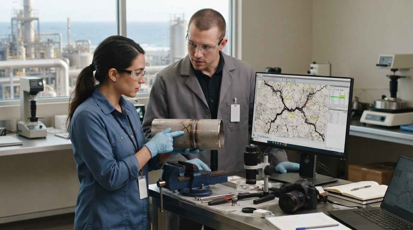

A functional prototype is a physical embodiment of a design built to demonstrate that the product works as intended, so it validates behaviour, mechanisms and interactions long before any tooling is committed. In industrial product development, the word “prototype” is used loosely for everything from a foam block that only shows shape to a near-series unit assembled from injection-moulded parts. That ambiguity is expensive: teams frequently believe a prototype has confirmed something it never tested, then discover the gap during industrialisation, when changes cost orders of magnitude more than they would have on paper or in an early iteration.
PROTOTYPING
Do you want to know what a functional prototype really validates? Discover our prototyping service

What a functional prototype is and what it is not
Before discussing validation, the object itself has to be defined precisely, because most costly errors begin with a category mistake. A functional prototype is not merely “a prototype that moves”; it is a deliberate representation of the working principles of a product, built at a chosen level of fidelity so that specific questions about performance and behaviour can be answered with physical evidence. Understanding where it sits relative to appearance models and proofs of concept, and how its fidelity maps onto readiness, is the foundation for everything that follows.
The functional prototype as a physical test of design hypotheses
A functional prototype exists to convert design hypotheses into measurable behaviour. Every product carries assumptions, que a latch will hold under repeated use, that a pump will deliver a target flow, that two subassemblies will align when mated, that a user can operate a control without instruction. A functional prototype makes those assumptions testable by embodying the mechanism, the kinematics and the interfaces in hardware, even when the materials or manufacturing routes differ from the final product. This is the essence of prototyping: producing a representative artefact whose purpose is to generate evidence, not to look finished.
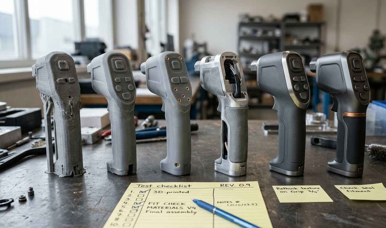
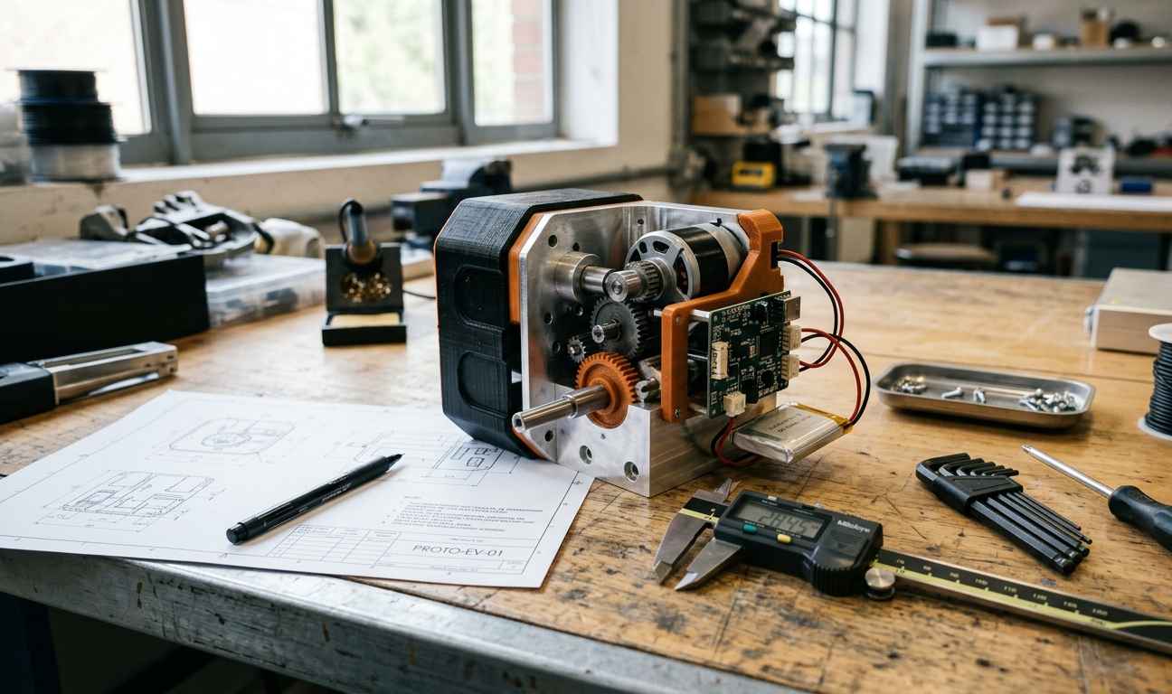
Fidelity is the key variable. A low-fidelity functional prototype might use 3D-printed housings and off-the-shelf motors to prove that a mechanism sequences correctly; a high-fidelity one might integrate near-final electronics, representative seals and calibrated sensors to characterise performance under representative conditions. The level of fidelity should be chosen from the question being asked, not from the desire to impress. A prototype built to answer “does the mechanism work?” does not need series material; a prototype built to answer “will the seal survive the operating temperature?” absolutely does.
A functional prototype is only as trustworthy as the question it was built to answer; fidelity that is irrelevant to that question adds cost without adding evidence.
This framing connects naturally to technology readiness levels (TRL), a scale that describes how mature a technology is, from basic principles observed (low TRL) to a system proven in its operational environment (high TRL). A functional prototype typically advances a design through the middle of that scale, from a validated concept toward a system demonstrated in a relevant or operational setting. Naming the TRL you are targeting forces honesty about what the prototype must contain to be credible, and it exposes the temptation to claim high readiness from a unit that only demonstrates a principle. A well-designed advanced functional prototype for liquid dispensing illustrates the difference: it works, it demonstrates, and it does so at a fidelity chosen to match the decisions it must support.
The functional prototype versus the aesthetic model and the proof of concept
The functional prototype occupies a distinct place between two other artefacts that are routinely confused with it. An aesthetic or appearance model reproduces form, finish, colour and perceived quality, but it does not work; it answers questions about styling and human perception, not about function. A proof of concept, by contrast, isolates a single risky principle to show that it is physically possible at all, often with no attempt at packaging, ergonomics or integration. Both are legitimate and useful, but neither validates that the product functions as a whole.
A proof of concept is deliberately narrow: it de-risks the one thing nobody yet knows how to do, a novel actuation, an unproven chemistry, a marginal thermal path, and it is complete once that uncertainty is resolved. The functional prototype is broader. It assumes the core principles are feasible and asks whether they integrate into a coherent, operable device: whether the mechanism, the structure, the interfaces and the user interaction cooperate under representative use. Confusing the two leads teams to over-scope a proof of concept or, worse, to treat a narrow proof of concept as if it validated the whole product.
The distinction matters commercially as well as technically. Investors and internal stakeholders often see a beautifully finished appearance model and assume the product is nearly ready; engineers who know it does not function understand it validates nothing about performance. Being explicit about which artefact is on the table, appearance model, proof of concept, or functional prototype, aligns expectations and prevents decisions being made on the wrong evidence. This clarity is also what allows a functional prototype to be scoped correctly in the first place, so that it validates what it must and does not pretend to validate what it cannot.
What a functional prototype does and does not validate
With the object defined, the central question becomes practical: which conclusions can be drawn from a functional prototype, and which cannot be drawn from it alone? The honest answer depends on how representative the prototype is of the series product in material, process and condition. A high-fidelity unit validates more; a 3D-printed unit validates less about series behaviour even when it validates a great deal about design intent. The two H3 sections below separate the confident conclusions from the ones that require additional, specific evidence, and the comparison table makes the boundary explicit.
What the functional prototype genuinely validates
A functional prototype is strongest at confirming that the design does what it was conceived to do. It validates function and mechanism: whether the kinematics sequence correctly, whether forces and motions are transmitted as intended, whether a device performs its primary task. It validates interaction and ergonomics: whether controls fall to hand, whether operating effort is acceptable, whether the interface is legible and the workflow intuitive. These are behavioural questions, and behaviour is exactly what a working unit reveals.
It also validates assembly and fits at the level of geometry and architecture. Building the prototype exposes whether parts can actually be assembled in a sensible order, whether clearances are sufficient for hands and tools, whether connectors reach, and whether the product architecture, the partition of the product into subassemblies and interfaces, holds together. Many integration problems are invisible in CAD and obvious the moment a physical unit is mated. A functional prototype surfaces them early, when the fix is a design change rather than a tooling change.
A functional prototype reliably validates design intent, function, interaction, architecture and fit at the geometric level, because these depend on how the design is conceived, not on which material or process makes the final part.
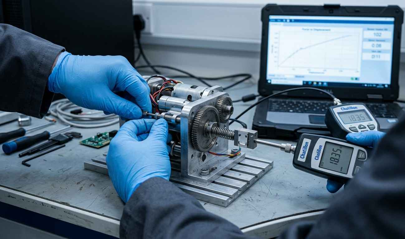
Within limits, a functional prototype can also validate some performance under representative conditions and can confirm or refute specific design hypotheses. If the unit uses representative components in the domain being tested, for example the actual pump, valve and tubing of a fluidic device, then measured flow, pressure or cycle behaviour can be meaningful. The evaluation of a device such as the evaluation and optimisation of a new disinfection device shows how a working unit can characterise real performance when the tested subsystem is representative. The essential discipline is to know exactly which variables are representative and to restrict conclusions to those.
What the functional prototype does not validate on its own
The limits of a functional prototype are defined by everything that depends on the final material and process rather than on the design. If the prototype is 3D-printed in a polymer that is not the series material, it does not validate the mechanical properties, strength, stiffness, creep, chemical resistance, of the injection-moulded part that will ship. A 3D-printed housing may pass a hand test and still be nothing like the moulded part in fatigue behaviour, surface finish or dimensional stability. The prototype validated the design; it did not validate the series part.
Equally, a functional prototype does not by itself validate series manufacturing process capability. Whether a moulding process can hold the required tolerances at scale, whether a weld or bond is repeatable across thousands of units, whether cycle time and yield are economic, none of this is proven by a handful of prototype parts made by different methods. Series-part tolerances, governed by standards such as the ISO 286 system for limits and fits, are a property of the production process, not of a prototype produced by milling or additive manufacturing. Durability and fatigue life are similarly out of scope unless the prototype is specifically built and instrumented to test them over representative cycles.
| Aspect | What a functional prototype does validate | What it does not validate by itself |
|---|---|---|
| Function and mechanism | That the kinematics, forces and primary task work as designed | Long-term reliability of the mechanism at series quality |
| Ergonomics and interaction | Operability, control layout, effort and workflow | Perceived quality of the final finish and materials in use |
| Fit and assembly | Geometric clearances, assembly order and interfaces | Series-part tolerances (e.g. ISO 286) held in volume production |
| Material | Suitability of the design for its intended loads (if representative) | Series material properties when a different material/process is used |
| Manufacturing process | That parts can be made and assembled at prototype scale | Process capability, yield and repeatability at series volume |
| Compliance | Readiness to enter formal testing; obvious gaps | Homologation and regulatory compliance without certified testing |
Finally, a functional prototype validates neither real cost at volume nor formal regulatory compliance. Unit cost is dominated by tooling amortisation, cycle time, material selection and assembly labour at scale, factors that a one-off prototype cannot reveal. Homologation against safety, electromagnetic or environmental standards requires testing on representative, series-intent units under accredited conditions; a prototype can indicate readiness and flush out obvious problems, but it cannot substitute for certified verification. Recognising these boundaries is not pessimism, it is what keeps a validation plan honest and prevents the most expensive mistakes, which are the subject of the next section.
TELL US ABOUT YOUR CASE
Do you have a product to validate with a prototype? Send us your case and we will propose a prototyping and testing plan
Mistakes that inflate cost and how to iterate toward pre-series
Most cost inflation in product development does not come from a single dramatic failure; it accumulates from a series of small misjudgements about what a prototype proved. The pattern is consistent: a decision is made on the strength of a prototype that never tested the relevant variable, and the correction surfaces later, when tooling exists and change is expensive. The two H3 sections below catalogue the recurring mistakes and then describe how disciplined iteration, simulation and a design verification plan carry a validated design safely into pre-series.
Frequent mistakes with the functional prototype that inflate development cost
The most common and most expensive mistake is confusing an aesthetic or 3D-printed unit with a representative functional prototype. A stakeholder sees a finished-looking or working-looking model and greenlights investment, unaware that the material, process and tolerances bear no relation to the series product. A closely related error is validating with non-representative materials or processes and then extrapolating series behaviour from prototype results, assuming that because a machined aluminium bracket held, the die-cast production bracket will too, or that because a 3D-printed clip snapped into place, the injection-moulded clip will have the same stiffness and fatigue life.
The costliest prototypes are not the ones that fail; they are the ones that appear to succeed while silently testing the wrong variable.
A second cluster of mistakes concerns test discipline. Not defining acceptance criteria before testing means the team decides after the fact whether the result is “good enough”, which invites optimism and hides marginal performance. Not isolating the variable under test, changing material, geometry and load simultaneously between iterations, makes it impossible to know what caused a result, so lessons cannot be transferred. Both errors turn expensive prototype builds into ambiguous evidence, forcing additional iterations that a clear test plan would have avoided.
A third cluster concerns manufacturing and scope. Skipping design for manufacturing until after the prototype is “finished” defers manufacturability problems to the most expensive possible moment, where fixing them may mean redesigning parts that are already being tooled. Committing tooling too early, ordering moulds before the design has stabilised through iteration, converts every subsequent change into a tooling modification or a scrapped tool. Over-engineering the prototype, meanwhile, wastes time and money making the unit more capable, more finished or more instrumented than the current question requires, delaying the evidence that actually matters. Each of these mistakes is avoidable, and each is far cheaper to prevent than to correct. Structured mechanical development exists precisely to sequence these decisions so that manufacturability, material selection and tooling commitment happen in the right order rather than under schedule pressure.
Genuinely validating those properties needs representative parts: it’s the same logic behind how a substitute material is characterised and validated before production.
Iteration, simulation and a DVP that carry the functional prototype to pre-series
A functional prototype is not a single event but a stage in a loop: build, test against defined criteria, learn, redesign, and repeat at rising fidelity until the design is stable enough to justify pre-series. Early iterations answer feasibility and function at low fidelity, often with 3D-printed parts; later iterations raise fidelity toward series material and process to close the gaps the table identified. The jump to pre-series, a small run made with production-intent tooling and materials, should happen only when the remaining risks are about volume manufacturing and statistics, not about whether the design works.
Simulation and physical prototyping are complementary rather than alternatives. Finite element and multiphysics simulation explore many design variants quickly and predict stress, deflection, thermal behaviour and fatigue where physical testing would be slow or destructive; the functional prototype then validates whether the simulation’s assumptions held in the real, assembled system. Correlating measured prototype behaviour against simulated predictions is powerful: it either confirms the model, allowing confident extrapolation, or reveals where the model was wrong, improving every subsequent prediction. Used this way, simulation reduces the number of physical iterations needed and focuses each build on the variables that models cannot yet predict reliably.
Iteration is not indecision; each cycle should retire a specific, named risk, and the design is ready for pre-series only when the remaining risks concern volume production rather than function.
A design verification plan (DVP) is the instrument that ties this together. A DVP is a structured matrix that lists every requirement, the method by which each will be verified, analysis, simulation, inspection or physical test, the acceptance criteria, and the artefact on which verification occurs, whether a functional prototype, a pre-series unit or a certified test sample. It forces the team to decide, in advance, which requirements a functional prototype can validate and which must wait for representative series parts or accredited testing. That single act of planning prevents the category mistakes described above, because it makes explicit what each artefact is expected to prove and what it is not.
Validate the right thing at the right time
A functional prototype is one of the most valuable instruments in product development, but only when its evidence is read for exactly what it is. It validates design intent with confidence: function, mechanism, interaction, ergonomics, architecture and geometric fit are all revealed the moment a working unit exists, and many of these are impossible to confirm any other way. Used at the right fidelity, it also characterises real performance in the specific subsystems that are representative, and it advances a design along the technology readiness scale from concept toward a demonstrated system. Those are genuine, bankable gains, and they justify building prototypes early and iterating deliberately.
What a functional prototype does not do, on its own, is validate series material properties when the prototype uses a different material or process, series manufacturing process capability, series-part tolerances, durability or fatigue life unless specifically tested, real cost at volume, or regulatory homologation. Treating a prototype as if it had proven these things is the root of most cost inflation, because the correction always arrives late, when tooling and commitments are already in place. The discipline that prevents this is neither exotic nor expensive: define acceptance criteria before testing, isolate the variable under test, choose fidelity from the question rather than from ambition, apply design for manufacturing early, delay tooling until the design is stable, and record every requirement in a design verification plan that names how and on what artefact it will be proven.
If you’re about to validate a functional prototype and need to be sure what it must prove before you commit tooling, tell us the product and its requirements: we’ll return a validation plan setting out which tests to run, at what fidelity and in what order, so you don’t pay for changes once they’re expensive.
Frequently asked questions about the functional prototype
Does a functional prototype validate series material properties?
Not by itself, and only when the prototype is made from the same material and process as the series part. A functional prototype built by 3D printing or machining validates the design’s function and geometry, but it says little about the strength, stiffness, fatigue and chemical resistance of an injection-moulded or die-cast production part. To validate series material properties you need representative parts made by the intended process, tested against defined criteria. This distinction is central to any effort to prevent failures in industrial products, because most field failures trace back to a property that a non-representative prototype was assumed, but never proven, to possess.
What is the difference between a functional prototype and a minimum viable prototype?
A minimum viable prototype is a functional prototype scoped to the smallest build that answers the current highest-priority question. Rather than a full-featured unit, it contains only the elements needed to test one critical hypothesis, a mechanism, an interaction, a performance target, so that evidence is obtained quickly and cheaply before further investment. A full functional prototype may integrate many subsystems; a minimum viable prototype (MVP) deliberately strips the build to essentials. Both are functional; they differ in scope and in the breadth of what they are intended to validate.
Can a 3D-printed part be a valid functional prototype?
Yes, provided its conclusions are restricted to what the process can legitimately represent. A 3D-printed functional prototype is excellent for validating geometry, mechanism, assembly order, clearances and ergonomics, and it is fast and inexpensive to iterate. It is not valid for concluding anything about series material properties, injection-moulded tolerances or long-term durability, because 3D printing produces different mechanical behaviour and surface characteristics from most series processes. The part is valid as a functional prototype as long as the team knows which variables are representative and confines its conclusions to those.
When should acceptance criteria for a functional prototype be defined?
Acceptance criteria should be defined before the prototype is built and tested, never after the results are seen. Deciding in advance what a successful outcome looks like, a target flow, a maximum operating force, a required clearance, a number of cycles without failure, prevents optimistic reinterpretation of marginal results and makes each test conclusive. Criteria set after the fact tend to be adjusted to whatever the prototype achieved, which hides risk and defers failures to a more expensive stage. Defining them up front is also what makes a design verification plan usable rather than decorative.
When is a functional prototype ready to move to pre-series?
A functional prototype is ready for pre-series when the remaining risks concern volume manufacturing rather than whether the design works. That means function, ergonomics, assembly and architecture have been validated, design for manufacturing has been applied, representative testing has closed the material and process gaps that matter, and the design has been stable across iterations without further significant change. At that point the open questions are process capability, tolerances at volume, yield and cost, which only production-intent tooling and a pre-series run can answer. Moving earlier, while the design is still changing, is the classic way of committing tooling too soon and inflating cost.