
Corrosion rate is the loss of thickness of a metal per unit of time, in millimetres per year, and it is measured with electrochemical tests that record the current of the reaction without waiting for visible damage.
That is the underlying difference from an exposure test. The corrosion of a metal in an aqueous medium is an electrochemical process, with an anodic reaction that oxidises the metal and a cathodic one that balances it, and electrochemical tests act directly on that pair of reactions to measure how fast they occur.
Within materials analysis and testing they are the fast route to two specific questions, how fast this material corrodes in this medium and which mechanism is in control, general or localised corrosion. That second answer is the one that changes a material decision.
ELECTROCHEMICAL TESTS
Do you need to know how fast a material corrodes in your environment and by what mechanism? Take a look at our electrochemical tests

How corrosion rate is measured
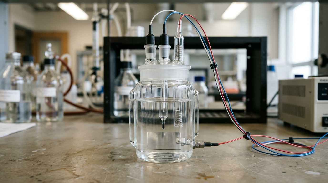
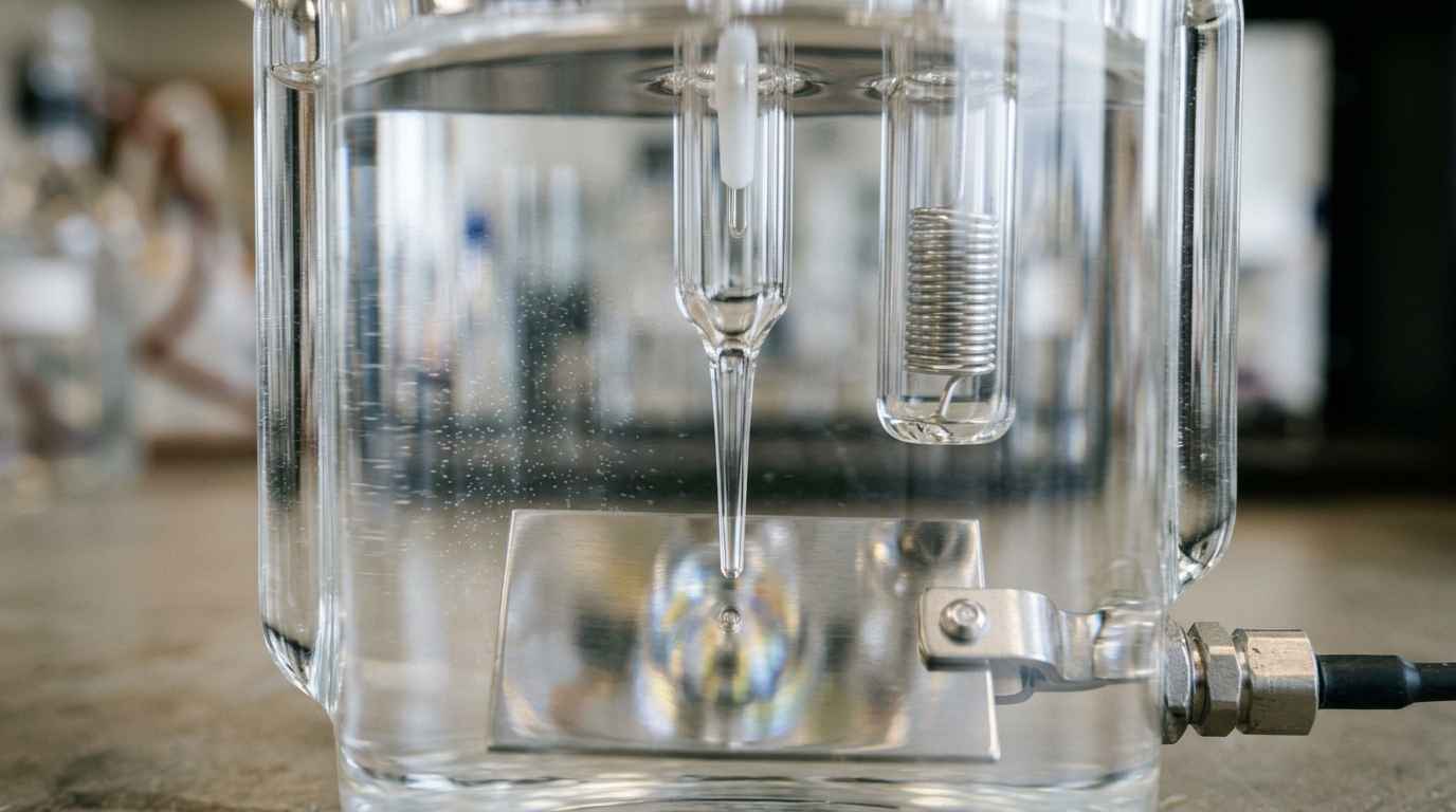
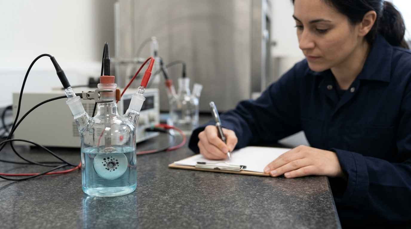
An electrochemical test measures current and potential on a specimen immersed in the electrolyte of interest, with three electrodes, the working electrode that is the sample, a reference electrode that fixes the potential and a counter electrode that closes the circuit. The whole family of tests consists of disturbing that system in a controlled way and reading how it responds.
The starting value is the corrosion potential, the one the sample takes up when nothing is applied to it. It shows the thermodynamic tendency of the material in that medium, but on its own it says nothing about the rate. Two materials with similar potentials can corrode at very different rates, and confusing potential with rate is the most widespread misunderstanding about these tests.
There is one variable of the set-up that weighs as much as the material, dissolved oxygen. In neutral, aerated media the cathodic reaction that sustains corrosion is oxygen reduction, so the amount of oxygen available limits the rate of the whole process. Testing the same specimen in the same electrolyte aerated or deaerated can give rates that differ by an order of magnitude, and neither of them is wrong, they correspond to two different services.
That is why aeration is part of the definition of the test and not one of the details of the procedure. A closed circuit with no water renewal, an open tank and a buried pipe are three scenarios with very different oxygen availability. Deciding which one is reproduced is a prior engineering decision, and it should be written into the report alongside the result.
Corrosion rate, from potential to millimetres per year
To go from potential to rate, the system has to be moved and the current it takes to move it has to be measured. If you apply a small potential shift around the corrosion potential, the current that flows is proportional to how easily the reactions proceed, and the rate comes from that proportion.
The anodic reaction being measured is the oxidation of the metal itself, so the current is a direct measure of how much material is being lost. Once the corrosion current density is known, it is converted into thickness loss per year using the equivalent weight and the density of the material, which allows different alloys to be compared in the same unit.
ASTM G102 sets out precisely the derivations of those equations and the methods for estimating the Tafel slopes involved in the calculation. It is the reference that turns an electrical measurement into engineering data, and the reason two laboratories can give comparable figures.
Polarisation resistance and general corrosion rate
Polarisation resistance is the slope of the potential versus current density curve in the vicinity of the corrosion potential. The higher that resistance, the harder it is for the reaction to proceed and the slower the corrosion. It is a quantity measured in minutes, which allows a system to be followed over time.
The relationship between polarisation resistance and corrosion current is established with the Stern and Geary coefficient, which depends on the anodic and cathodic Tafel slopes. ASTM G59 sets the procedure for the potentiodynamic polarisation resistance measurement and is also used to verify the equipment and the technique, so that the figure obtained is reproducible and not an artefact of the set-up.
Polarisation resistance measures the general corrosion rate at the moment of the test and in that specific electrolyte. It is a kinetic snapshot, not a prediction of service life.
The most direct application is comparison. Since the measurement is fast and minimally invasive, it serves to rank alloys, finishes or inhibitors in the same medium and with the same criterion, which is what was done in the corrosion resistance comparison to select the optimum surface finish. For continuous monitoring in a plant it is also the usual technique, because it does not destroy the specimen and can be repeated.
Potentiodynamic polarisation and localised corrosion
Potentiodynamic polarisation and impedance are the two techniques that account for most industrial use, and they answer different questions. Potentiodynamic polarisation sweeps a wide potential range and describes the behaviour of the bare metal, including its tendency to pit. Impedance applies a small alternating signal at many frequencies and mainly describes the condition of the barrier that protects the metal.
Passive region and pitting potential in stainless steels
When the potential is swept towards more positive values, a stainless steel or an aluminium alloy shows a zone where the current stops rising, the passive region, where a very thin oxide layer slows dissolution. The width of that region and the current level that characterises it show how much protection passivation provides in that medium.
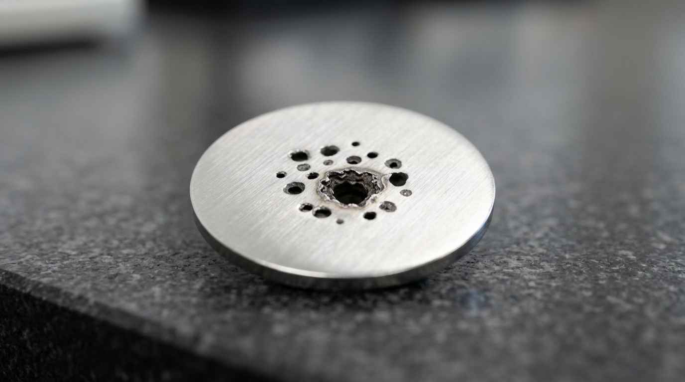
If the potential keeps rising, a point is reached where the current shoots up, the passive layer breaks down locally and pitting starts. That pitting potential is the figure that really matters in chloride media, because localised corrosion perforates a thickness in a short time without the overall mass loss being noticeable.
Reversing the sweep also gives the potential at which the pit repassivates. The gap between the potential at which the layer breaks down and the potential at which it repassivates measures the material’s ability to repair itself, and it is the criterion that separates two stainless steels that would look equivalent in a mass loss test. A different mechanism, stress corrosion cracking, also requires mechanical load and is not detected with these curves.
Galvanic corrosion between metals in contact
The galvanic couple has its own set-up. When two different metals are in electrical contact within the same electrolyte, the more active one corrodes to protect the other, and what is measured is not a curve but the current flowing between them with a zero resistance ammeter. The critical figure there is the area ratio, because a small anode connected to a large cathode concentrates all the corrosion on a small surface and perforates quickly. A bolt of one material and a sheet of another is the textbook case, and the polarisation curve of each metal on its own does not anticipate it.
TELL US ABOUT YOUR CASE
Do you have a coating that fails earlier than expected and cannot tell whether the problem is the film or the substrate preparation? Send us samples and a description of the service environment and we will propose the test plan
Electrochemical impedance spectroscopy on coatings
Electrochemical impedance applies an alternating signal of very small amplitude and covers a wide range of frequencies, so it separates phenomena that occur at different speeds. In a painted system that makes it possible to tell apart the resistance of the film, its capacity to absorb water and what happens at the interface with the metal, which is where disbonding starts.
Impedance on highly insulating coatings
It is the right technique when the coating is highly insulating, because direct current measurements have little signal against a high impedance. Following the evolution of the spectrum during immersion detects the degradation of the barrier before any visible defect appears, as in the evaluation of coatings on steel against corrosion. When a failure of the film has to be separated from one of the substrate preparation, it is completed with coating characterisation.
Interpreting the impedance spectrum and verifying it
Interpreting it does not always require a complex model. The value of the impedance modulus at low frequency works as a practical indicator of the condition of the barrier, and following how that value falls during immersion ranks coatings without having to fit a complete equivalent circuit. Detailed fitting adds value when you need to know whether the deterioration comes from porosity of the film or from loss of adhesion at the interface.
The reliability of a spectrum depends on the equipment and on the model fit, and for that there is a specific practice, ASTM G106, for verifying the algorithm and the electrochemical impedance measurement equipment. Without that verification, a fit can give parameters that look good numerically and have no physical meaning.
When to choose an electrochemical test and when not to
The electrochemical test is the option when you need a rate, a mechanism or a fast comparison between materials in a known medium. It stops being the option when what you have to demonstrate is compliance with a specification that requires a specific exposure test, or when the real failure is not electrochemical.
Electrochemical test versus accelerated corrosion test
The two approaches do not compete, they answer different questions. An exposure test in a chamber subjects the complete part to the aggressive environment and delivers hours until a defect appears, with a visual criterion, as detailed in the accelerated salt spray corrosion test. That is valid for classifying finishes and for meeting a specification, but it gives neither rate nor mechanism.
The electrochemical test delivers rate and mechanism in hours, on a specimen and in a defined electrolyte, but it does not reproduce the geometry of the part or the wetting and drying cycles of the real environment. The usual combination is to use the electrochemical test to choose between candidates and the exposure test to validate the one chosen, which is the order a corrosion protection assessment usually follows.
| Technique | What is applied | What it delivers | When to use it | Main limit |
|---|---|---|---|---|
| Corrosion potential | Nothing, it is only measured | Thermodynamic tendency and stabilisation | Starting point of any test | Says nothing about rate |
| Polarisation resistance | Small shift around the potential | General corrosion rate | Comparing materials and inhibitors, monitoring | Assumes uniform corrosion |
| Potentiodynamic polarisation | Wide potential sweep | Passive region and pitting potential | Stainless steels and aluminium in chloride media | Alters the surface, single use specimen |
| Cyclic polarisation | Forward and reverse sweep | Repassivation capacity | Separating alloys for localised corrosion | Result sensitive to the sweep rate |
| Electrochemical impedance | Small alternating signal at several frequencies | Condition of the barrier and the interface | Painted systems and insulating coatings | Requires a fitting model and its verification |
Limits of the method and interpretation errors
The first limit is stated by the standard itself. The polarisation resistance method may not be appropriate for all materials or in all environments, and it has known biases due to the solution resistance and the electrode capacitance. In poorly conducting electrolytes, the potential drop in the solution itself distorts the measurement if it is not compensated.
The second is conceptual. The general corrosion rate delivered by the measurement spreads the loss over the whole surface, so a material suffering pitting can show a low average rate and be perforating at one point. When the risk is localised, the relevant figure is not the average rate but the pitting and repassivation potentials.
The third is representativeness. The specimen measures the material, not the part, so it does not include welds, cut edges, contact zones between different metals or crevices where electrolyte accumulates. If the failure in service happens exactly there, the test on a flat specimen will give a correct result and a wrong conclusion.
There is a fourth limit, comparability between reports. A potential means nothing unless it is stated against which reference electrode it was measured, because each reference has its own scale. Comparing a pitting potential measured against saturated calomel with another measured against silver/silver chloride without converting the scale produces differences of hundreds of millivolts that do not exist. When you receive a report, check that it states the reference electrode, the electrolyte composition, the temperature and the exposed area, which are the four data without which the figure cannot be reused.
A low corrosion rate does not rule out perforation. When the mechanism is localised, what decides is the pitting potential and the repassivation capacity, not the average thickness loss.
From electrochemical data to a material decision
A well designed electrochemical test leaves three things, a rate in engineering units, an identified mechanism and a ranking of the candidates you were assessing. With that you decide which material or which finish moves on to the validation stage, and the rest are discarded without waiting weeks of exposure.
What most affects the result is the definition of the electrolyte. The test measures the material in whatever medium you give it, so a composition, temperature or pH that does not match the real service produces a correct number with no value. Before testing, it has to be agreed which medium is considered representative and why.
Prepare a description of the service environment with its composition, temperature and aeration, two or three material or finish candidates and, if it exists, the failure history of the installation. With that the appropriate techniques are defined, rate and mechanism are measured on the same basis and you receive a comparison with the recommendation and its limits stated explicitly.
Frequently asked questions about corrosion rate
Can an electrochemical test predict the service life of a part?
Not directly. It delivers the corrosion rate at the moment of the test and in the electrolyte used, and that rate changes with temperature, aeration, deposit formation and the wetting and drying cycles of the real service. It is useful for comparing materials and detecting the mechanism, which is what allows an order of magnitude to be estimated. A service life forecast also requires prolonged exposure under representative conditions and, when the component works under load, a separate step to assess stress corrosion cracking.
What size and preparation does the specimen need?
A flat surface of a few square centimetres that can be sealed against the cell is enough, but preparation matters more than size. The surface finish has to be reproduced identically on all samples, because roughness changes the real area and with it the current density. In real parts a coupon is extracted from the zone of interest and its orientation is documented, since the microstructure and rolling direction influence the result, as with any test on metallic materials and alloys.
What factors determine the cost of measuring corrosion rate?
The cost depends on the number of materials to compare, the techniques the question calls for and the immersion time. A polarisation resistance measurement on three candidates in one medium is the most contained scenario, because the measurement is fast and the specimen small. It rises with cyclic polarisation, which uses up one specimen per test, and with impedance followed over weeks of immersion, which ties up the cell and the equipment for all that time.
What risk do you take if you choose the material with a salt spray test alone?
You risk choosing well against the test criterion and badly against the service. A finish can withstand many hours of salt spray and perforate through pitting in a medium with chlorides and temperature, because the chamber classifies by appearance and not by mechanism. The reverse risk also exists, discarding a material that performs worse in the chamber but repassivates well in the real medium. Measuring the mechanism before ranking by hours avoids both mistakes.
How long does it take to measure corrosion rate?
Typical lead times range from one to four weeks depending on the techniques and the immersion time the case requires. Potential and polarisation resistance measurements are obtained on the same day once the sample has stabilised. Cyclic polarisation curves add specimen preparation, and impedance monitoring of a coating lasts as long as the scheduled immersion. For a stopped line or a batch in quarantine there is an urgent 24 to 72 hour option covering the scope that can be closed in that time.