
Prototyping technologies are the methods used to build a real part before you invest in series tooling, and each one imposes its own limits on tolerance, material, finish and cost per volume. Choosing well is not choosing the most modern option, it is choosing the one that answers the question you have open.
Checking that a housing fits its cavity, measuring how much load a mounting bracket takes, or finding out whether a surface feels right to the end user are different objectives, and each one tolerates some deviations and not others. Product development stalls when the technology you picked introduces behaviour the series part will never have.
The decision is taken during prototyping, usually with a tight deadline, several alternatives on the table and one constraint that weighs in almost every time: how many units you need. A single piece for a design review and a batch of thirty for a test campaign are not built the same way, and that shows clearly in a Minimum Viable Prototype (MVP), where the method is chosen for what has to be proven.
PROTOTYPING AND PROTOTYPE MANUFACTURING
Torn between printing, machining and bridge tooling? Discover our prototyping and prototype manufacturing service

What sets one prototyping technology apart from another
Prototyping technologies differ along four measurable axes: the tolerance they can hold, the materials they give access to, the surface finish they leave, and the relationship between unit cost and number of units.
A prototype is not worth having because it looks like the final part, it is worth having because it reproduces the variable you are about to measure. If dimensional tolerance is what decides the assembly, any technology that cannot hold it is giving you an answer you cannot use.
Geometric, functional and pre-series prototypes ask for different things
A geometric prototype checks shape, volume and fit, and accepts almost any material that holds the geometry. A functional prototype has to survive the loads, temperatures and cycles of real use, so the material becomes decisive. A pre-series prototype must additionally be made by a process close to production, because what you are validating is no longer the design but the manufacturability.
A judgement error that is expensive to undo is asking a prototype for a conclusion its manufacturing process cannot support, as set out in what a functional prototype does and does not validate. When the test asks the part for something its material or method does not represent, the result tells you about the prototype, not about the product.
The four variables that decide the prototyping technology
The choice closes by answering four questions in order: what tolerance you need to hold, what material the part has to be in, what finish or texture has to be assessed, and how many units you will need. Answering them before asking for quotes keeps you from comparing offers that are not comparable.
Tolerance is the variable that rules options out first. A drawing that gives dimensions without individual tolerances is read against the general tolerances of ISO 2768-1, and if the part carries fits with an IT grade to ISO 286-1, some methods are simply out of the running. Geometry also has a say: thin walls, long overhangs, deep holes or fine threads shorten the list well before the budget does.
Material is the second filter, because some processes offer an “equivalent” material that is not the same one. A polyamide part printed and the same part injection moulded share a trade name and do not share behaviour: crystallinity, orientation and internal porosity change, and with them stiffness and impact resistance.
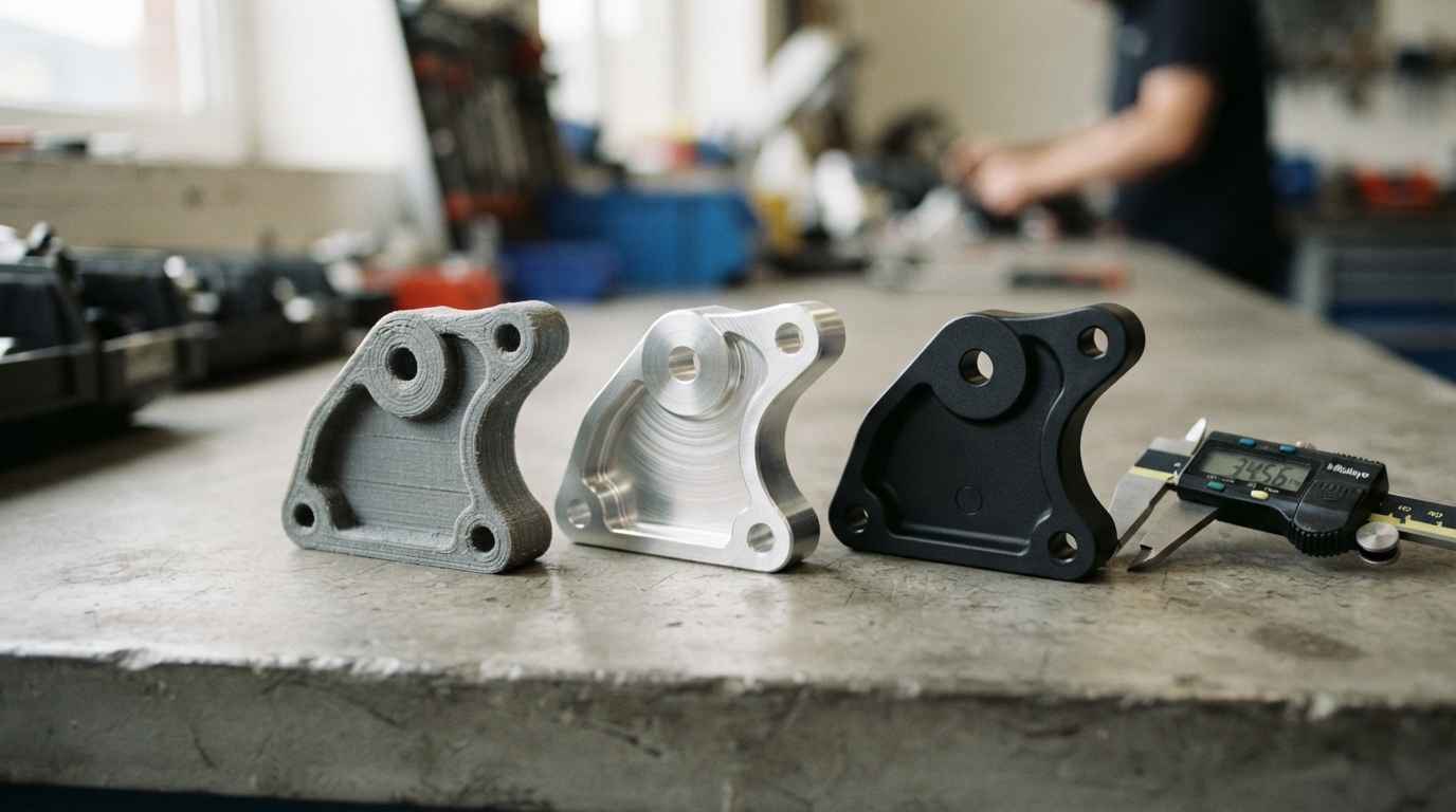
3D printing, machining and bridge tooling head to head
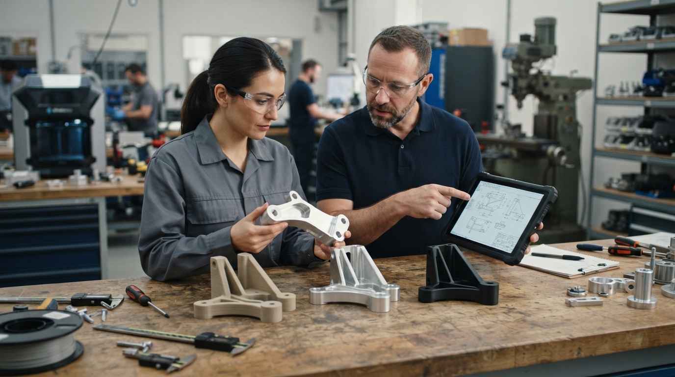
The three dominant families in industrial prototyping solve different problems: 3D printing buys time and geometric freedom, machining buys tolerance and real material, and bridge tooling buys a representative process and low unit cost in short runs. None of them is better in the abstract.
3D printing, when its finish and anisotropy are enough
3D printing builds the part by adding material layer by layer, with the processes and terminology classified in ISO/ASTM 52900, and its great advantage is that cost barely depends on how complex the shape is.
Its limits sit in three places. Anisotropy, because the part is weaker perpendicular to the layers and a delamination failure tells you about the method and not about the design. The finish, which carries the trace of the layers and usually needs post-processing. And tolerance, which depends on the material’s shrinkage and on part size.
Within 3D printing it is worth separating the technologies. Material extrusion leaves visible layers and is the cheapest; vat photopolymerisation gives fine detail and clean edges, with more brittle materials sensitive to light; powder bed fusion in polyamide produces parts without supports, with good strength and a characteristic matte texture.
CNC machining, fine tolerance and series material in a single part
Machining starts from a block of the final material and removes what is not the part, so it delivers the one thing no other prototyping technology gives without tooling: a part in the real material, with its heat treatment, its microstructure and its mechanical behaviour.
The cost of machining is measured in machine time and in set-ups, and the price is driven by the geometry and by the machinability of the material. Deep cavities, small internal radii or several clamping positions multiply the hours, and there are geometries that cannot be machined because the tool cannot reach them.
Tool access is exactly the constraint worth checking in the design before asking for a quote, the same way it is handled when applying design for manufacturing criteria. An internal radius that goes from two to four millimetres can remove a whole operation, and a dimension relaxed from a fine fit to a general tolerance can change the price without touching the function of the part.
Bridge tooling, when the real process is what you need
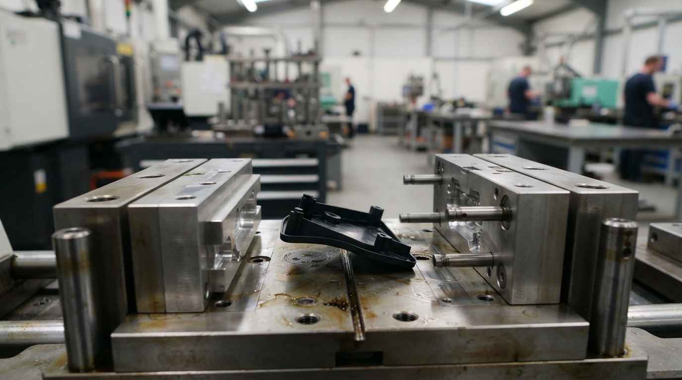
Bridge tooling is a mould in aluminium or soft steel, made with fewer operations and a shorter life than a series mould, that lets you injection mould or form parts by the definitive process for runs of a few thousand units.
When you mould, flow weld lines, sink marks in ribs and thick sections, stresses from uneven cooling, warping, ejection and ejector marks appear. These are process phenomena, not design phenomena, and no printed or machined part reveals them. If your doubt is whether the part can be manufactured at all, bridge tooling answers it.
There is an initial outlay on the tool that does not depend on the number of units, and in exchange unit cost drops to figures close to series production. The design and manufacture of a moulding tool to produce a part shows how that step is set up. Designing that bridge tool with the series mould already in view keeps it from inheriting errors that get carried over to the definitive one.
TELL US ABOUT YOUR CASE
Do you have a part in development and several possible technologies? Send us the model and the functional dimensions and we will propose the technology that settles it
Unit cost and lead time, the criterion that decides short runs
The cost of a prototype breaks down into two parts that behave in opposite ways: a fixed preparation cost (tooling, programming, set-ups) and a variable cost per unit.
How fixed cost crosses with the number of units
With almost no fixed cost and a high variable cost, 3D printing wins when you are talking about one to five parts. Machining has a moderate fixed cost (programming and set-ups are prepared once) and a variable cost that falls little with quantity, so it dominates the middle band and the parts where tolerance is non-negotiable. Bridge tooling inverts the relationship: high fixed cost, minimal variable cost, and it becomes the economical option from a few dozen parts upwards.
There is one cost that appears in no quotation: the iteration that was not needed. A cheap part that settles nothing forces you to repeat the whole cycle, while a more expensive one that closes the question first time saves weeks. A path such as the maturation of an idea, manufacture and validation of a prototype shows how those decisions get ordered.
Delivery lead time and the real time to a decision
The lead time that matters is not the manufacturing one, it is the one running from your decision to a conclusion. On top of machine hours you have file preparation, post-processing, dimensional verification and the test itself.
3D printing is the fastest at the gate, with lead times in days, and the one that needs most post-processing. Machining adds programming and set-up, but delivers a part ready to test. Bridge tooling is the longest because the tool has to be built before the first part, and in exchange the following ones come out in hours.
| Technology | Tolerance it holds | Materials it gives access to | Finish as delivered | Band of units where it competes |
|---|---|---|---|---|
| 3D printing by material extrusion | Wide, degrades across long dimensions | Prototyping thermoplastics, anisotropic behaviour | Visible layers, needs post-processing for appearance | 1 to 5 |
| 3D printing by vat photopolymerisation | Fine on small detail | Resins, brittle and light sensitive | Smooth, well defined edges | 1 to 10 |
| Powder bed fusion | Medium, uniform in all directions | Polyamide, no supports | Matte and slightly rough, uniform | 1 to 20 |
| CNC machining | Fine IT grades to ISO 286-1 | Final material, with its heat treatment | As machined, improvable without changing process | 5 to 50 depending on geometry |
| Bridge tooling | That of the series process | The production material and grade | That of the final part, with mould texture | Dozens to thousands |
What to check on the prototype depending on the technology
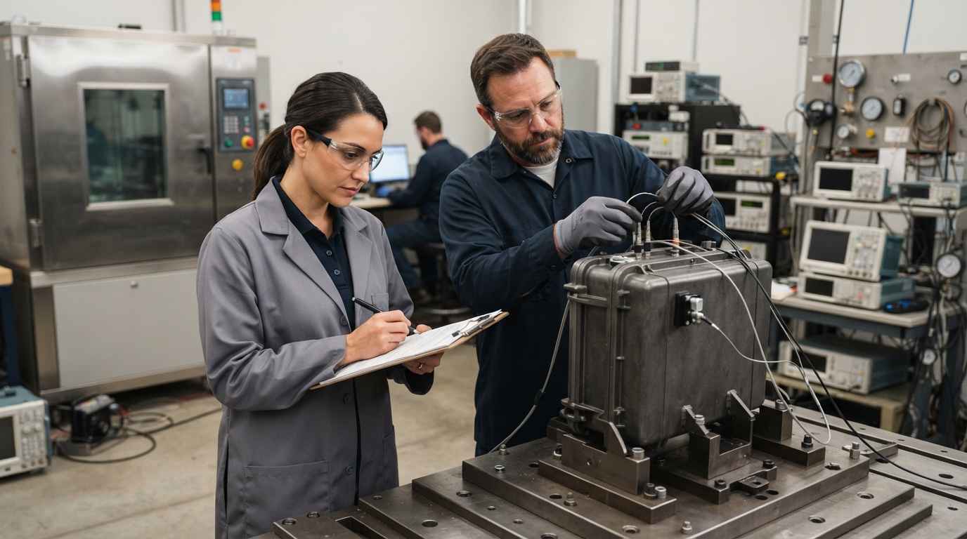
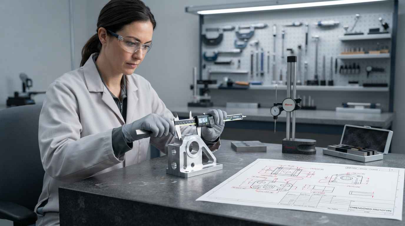
Every prototyping technology introduces its own deviations from the series part, and verification consists of measuring precisely those deviations before using the prototype to decide anything. An unverified prototype is a part with an unknown tolerance.
Dimensional verification does not confirm that the prototype is correct, it confirms how far it departs from the drawing. That figure is what later lets you tell a design failure apart from a failure in making the prototype itself.
Dimensional verification, what it covers and what it leaves out
The minimum check is to measure the functional dimensions, the ones that govern assembly and movement, and compare them with the drawing. Simple geometries need only workshop instrumentation; for complex surfaces or assemblies you turn to coordinate measurement or 3D scanning, which returns the point-by-point deviation against the model.
What dimensional verification does not cover is behaviour. A part within tolerance can break at half the expected load if its material is a substitute, and a part out of tolerance can work perfectly if the deviation falls where it does not matter.
When the prototype material invalidates the functional test
A functional test is only extrapolable to the series if the prototype’s material and process represent the production ones in the property being measured. When they do not, the test is useful for comparing design variants against each other, but not for claiming that the series part will hold.
In a part that will be injection moulded and is tested printed, some properties carry over reasonably well (apparent stiffness in gentle bending, ergonomics, fit) and others do not carry over at all (impact resistance, fatigue behaviour, sealing, fluid resistance). For the latter, the only route is machining in the final material or building the bridge tool, as described in automotive prototyping and its pre-production validations.
When the prototype’s objective is showing that the principle works, the criterion legitimately relaxes. A Proof of Concept does not need the series material because it is not validating the part, it is validating that the idea has somewhere to go. Confusing that stage with a product validation leads to presenting as settled something that was never checked.
The prototype material sets the scope of the conclusion. A test on a substitute material compares designs rigorously and authorises no claim about the strength of the part made in series.
Choosing the technology means deciding which question you want answered
Prototyping technologies are not ranked from worst to best, they are ranked by what each one can demonstrate. Fix the doubt that has to be closed first, translate that doubt into tolerance, material, finish and number of units, and the list of possible methods narrows itself. Then verify the prototype, because without knowing how far it departs from the drawing you cannot attribute a result either to the design or to the process. That order (doubt, variables, technology, verification) turns a prototype into a decision.
If you have a part in development and you are torn between printing it, machining it or releasing a bridge tool, send us the 3D model, the drawing with the functional dimensions and what you need to check with it, and we will propose the technology that answers it, the dimensional verification plan and the test that closes the question before you commit to series tooling.
Frequently asked questions
What can a prototype never tell you, even with the right technology?
A prototype tells you nothing about series variability, which is where rejects and customer claims show up later. Even when the technology represents material and process well, a single part does not show scatter between batches, the effect of tool wear, drift in moulding parameters or the difference between suppliers of the same material. It does not cover long service life either, because an accelerated test reproduces a mechanism and not the full calendar. Those questions need several parts, several batches and a sampling plan, not a better prototype.
When is machining a better choice than 3D printing?
Machining is the better choice whenever the conclusion depends on the material or on a fine tolerance. If you are going to measure strength, fatigue, sealing or a fit with an IT grade, machining delivers the part in the final material and with a tolerance printing cannot hold. It also helps when the part is large and long dimensions are critical, because the accumulated shrinkage of an additive process shows up exactly there. If the doubt is about shape, fit or ergonomics, printing is faster and cheaper and the result is just as valid. The decision gets much simpler if you have already applied design for manufacturing criteria and know which dimensions are functional and which are not.
What drives the cost of a prototype?
Four things govern the cost: the volume of material to remove or add, geometric complexity, the tolerance required and the number of units. Complexity makes machining expensive and is almost free in printing; a fine tolerance makes every process more expensive because it adds operations and verification; the number of units decides whether the fixed cost of a tool pays for itself. Finish is worth defining in the initial quote because it adds operations billed separately, especially if the prototype is going into a presentation or a user study, as happens when preparing a Minimum Lovable Product (MLP).
What do you risk by choosing wrongly among prototyping technologies?
You risk making a design decision on a figure that was not extrapolable. A prototype built by a method that does not represent the series produces two errors of opposite sign and equal cost: signing off a design that will fail in production, or redesigning and oversizing a part that never had the problem, because what was breaking was the prototype itself. On top of that comes the calendar cost, which is the one that hurts: every iteration based on an invalid figure consumes weeks and forces the whole cycle to be repeated with the tooling ever closer.
How long does it take to make and verify a prototype?
Lead time depends on the technology, there is no single range. A printed part is delivered in days, and with a basic dimensional check it closes inside the same week. A part machined in the final material takes one to two weeks, a little more if a mechanical test follows. A bridge tool is measured in weeks up to the first part, and from there the following ones come out in hours. If you have a deadline on you, agree the scope before manufacturing: request an assessment with the model and the functional dimensions and we will tell you the technology, the lead time and the verification plan.