
Material substitution is the engineered replacement of one material by another that meets the same functional requirements at lower weight, cost or complexity. Replacing a metal with a technical polymer makes sense when stiffness, service temperature and long-term load are moderate, and when you can validate the substitute on a representative moulded part.
The decision rarely fails on the datasheet and almost always fails on the details: fibre orientation, temperature dependence, creep under sustained load and moisture uptake behave nothing like a homogeneous alloy. Treating material substitution as a characterisation problem, not a procurement swap, is what separates a durable redesign from a warranty claim.
That approach sits inside a broader technological innovation workflow, where every candidate polymer earns its place through mechanical, thermal and ageing data measured on parts that reflect the real process. This article walks through when substitution pays off, when it does not, which engineering polymers compete, and how to prove that a replacement will hold.
BUSINESS INNOVATION SOLUTIONS
Do you need to replace a material with one that performs as well or better? Discover our business innovation solutions service

When replacing metal with a technical polymer makes sense
Replacing metal with a technical polymer makes sense when the part’s function tolerates lower stiffness and moderate temperature, and the redesign returns weight, cost, corrosion or integration benefits that metal cannot match cheaply. The strongest cases combine several of these drivers in a single component.
Lightweighting, cost and corrosion as substitution drivers
Density is the first lever. A glass-filled polyamide sits around 1.4 g/cm3 against roughly 7.8 for steel or 2.7 for aluminium, so a like-for-like volume can shed most of its mass. In automotive and capital goods that weight comes off unsprung or moving assemblies, where it compounds into lower inertia and energy use. Cost follows the process: injection moulding consolidates machining, casting, deburring and assembly into one shot, and the per-part economics improve sharply at volume.
Corrosion is the third driver and often the decisive one. A technical polymer does not rust, pit or galvanically couple, which removes plating, painting and sealing operations from the bill of materials. The trade-off is chemical compatibility, not electrochemistry, so the question shifts from “will it corrode” to “which fluids, temperatures and cleaning agents will it see”. INFINITIA has documented exactly this reasoning in a project on the selection of corrosion-resistant materials for new assemblies, where the substitution turned on service environment rather than nominal strength.
A polymer substitution succeeds when the driver is weight, corrosion or part count, and the mechanical demand stays within a margin you have measured, not one you have assumed from a supplier datasheet.
Function integration and part consolidation as insulation and design levers
Function integration is where polymers pull ahead of any metal redesign. A single moulded part can carry snap-fits, living hinges, cable guides, seals and mounting bosses that would otherwise be separate stamped or machined pieces. Consolidating five metal components into one polymer moulding removes fasteners, tolerances stack-ups and assembly labour at once, which is why electronics and consumer housings migrate first.
Electrical and thermal insulation add a second dimension. Most engineering polymers are dielectric by default, so they replace metal-plus-insulator subassemblies in connectors, housings and actuator bodies. When a design instead needs controlled heat dissipation, filled compounds can be tuned, and the property has to be measured rather than assumed, as in INFINITIA’s work on custom thermal conductivity testing in polymers to define new requirements. Getting the integration right early is the core of product improvement work, because every consolidated function is a tolerance and a failure mode you no longer have to manage downstream.
When substitution does not work
Substitution does not work when the part is stiffness-driven, runs hot for long periods, carries sustained or cyclic loads near the material limit, or must conduct. In those regimes a polymer either deflects too much, softens, creeps, fatigues or fails to move current, and no filler fully closes the gap.
Stiffness, modulus and high service temperature limits
Stiffness is the hardest ceiling. Steel’s elastic modulus is around 200 GPa and aluminium’s near 70; an unfilled engineering polymer sits between roughly 2 and 4 GPa, and even a 50% glass-filled grade rarely clears 15 to 20. If the design is deflection-limited rather than strength-limited, ribbing and wall geometry can recover some rigidity, but a direct swap into a stiffness-critical bracket will bend where the metal held.
Temperature is the second limit, and it acts twice. Short-term, heat deflection temperature under load (HDT, measured to ISO 75) tells you where the polymer loses form under stress; long-term, the continuous service temperature governs whether it survives thousands of hours without embrittling or degrading. A grade that passes a brief bench test at 120 C can still fail after months at 90, so both numbers matter and they are not interchangeable.
Creep, fatigue and conductivity as disqualifying factors
Creep is the failure mode engineers most often miss. Polymers deform continuously under constant load, so a bolted flange or a press-fit that holds on day one can loosen over months as the material relaxes, especially warm. Fatigue behaviour also differs: filled polymers have no clean endurance limit, and cyclic loading near a weld line or gate can propagate cracks well below the static strength.
Conductivity is a hard disqualifier. If the part must carry current, ground a circuit or dissipate concentrated heat through a thermal path, a standard polymer cannot do it and conductive fillers only partially bridge the gap at a cost and property penalty. When the load path is genuinely structural and safety-critical, metal testing to the same rigour, described under testing of metallic materials and alloys, remains the reference the polymer has to beat, not merely approach.
TELL US ABOUT YOUR CASE
Do you need to substitute a material without losing performance? Send us your case and we will propose a validated substitution plan
Which engineering polymers compete and the role of fibre fillers
An engineering polymer is a thermoplastic with mechanical and thermal performance high enough to carry load in service, and the competitive shortlist runs from polyamides through to PEEK. Choice depends on the temperature, stiffness, chemical exposure and budget the part actually demands.
PA, PPS, PEEK and the engineering polymer shortlist
Polyamide (PA6, PA66) is the volume workhorse: tough, machinable in moulded form and cheap, but it absorbs moisture and softens above roughly 120 to 150 C. Glass-filled polyamide (PA-GF) raises stiffness and heat resistance and is the default first candidate when replacing metal with a technical polymer. Polyphthalamide (PPA) pushes the temperature envelope higher while staying affordable relative to specialty resins.
Above that, polyphenylene sulphide (PPS) brings dimensional stability, chemical resistance and continuous use near 200 C, while PEEK is the high-temperature reference, holding structural properties past 250 C at a price that only demanding applications justify. On the commodity-engineering side, polycarbonate (PC) offers transparency and impact resistance, and polyoxymethylene (POM) delivers low friction, dimensional precision and fatigue resistance for gears, cams and moving mechanisms. Matching that shortlist to the load case is a materials characterisation task, backed by testing of plastics and polymers rather than supplier positioning.
Fibre fillers, anisotropy and flow orientation effects
Fibre fillers change the material from isotropic to directional. Glass or carbon fibres, typically 15 to 50% by weight, raise modulus, strength and heat deflection temperature, but they align with the melt flow during injection, so the part is stiffer and stronger along the flow direction than across it. That anisotropy means a single tensile number cannot describe the moulded part; properties depend on where and how the fibres landed.
A fibre-filled polymer is not one material with one strength; it is a directional composite whose real stiffness varies with flow orientation, wall thickness and gate position, which is why validating a substitute demands a moulded part, not a datasheet value.
Carbon fibre adds stiffness and some conductivity at higher cost; glass is the mainstream choice. Where the reinforcement content and architecture get more demanding, the behaviour approaches that of structural composites, and the same characterisation logic used in composite materials testing applies to predicting how the filled polymer carries load in the real geometry.
How to validate the substitute
Validating a substitute means measuring mechanical, thermal, creep, ageing and fatigue behaviour on a part that represents the production process, then comparing it against the metal’s real service envelope. Datasheet values describe an idealised specimen, not your component, so they anchor the shortlist but never close the decision.
Mechanical and thermal validation of the polymer
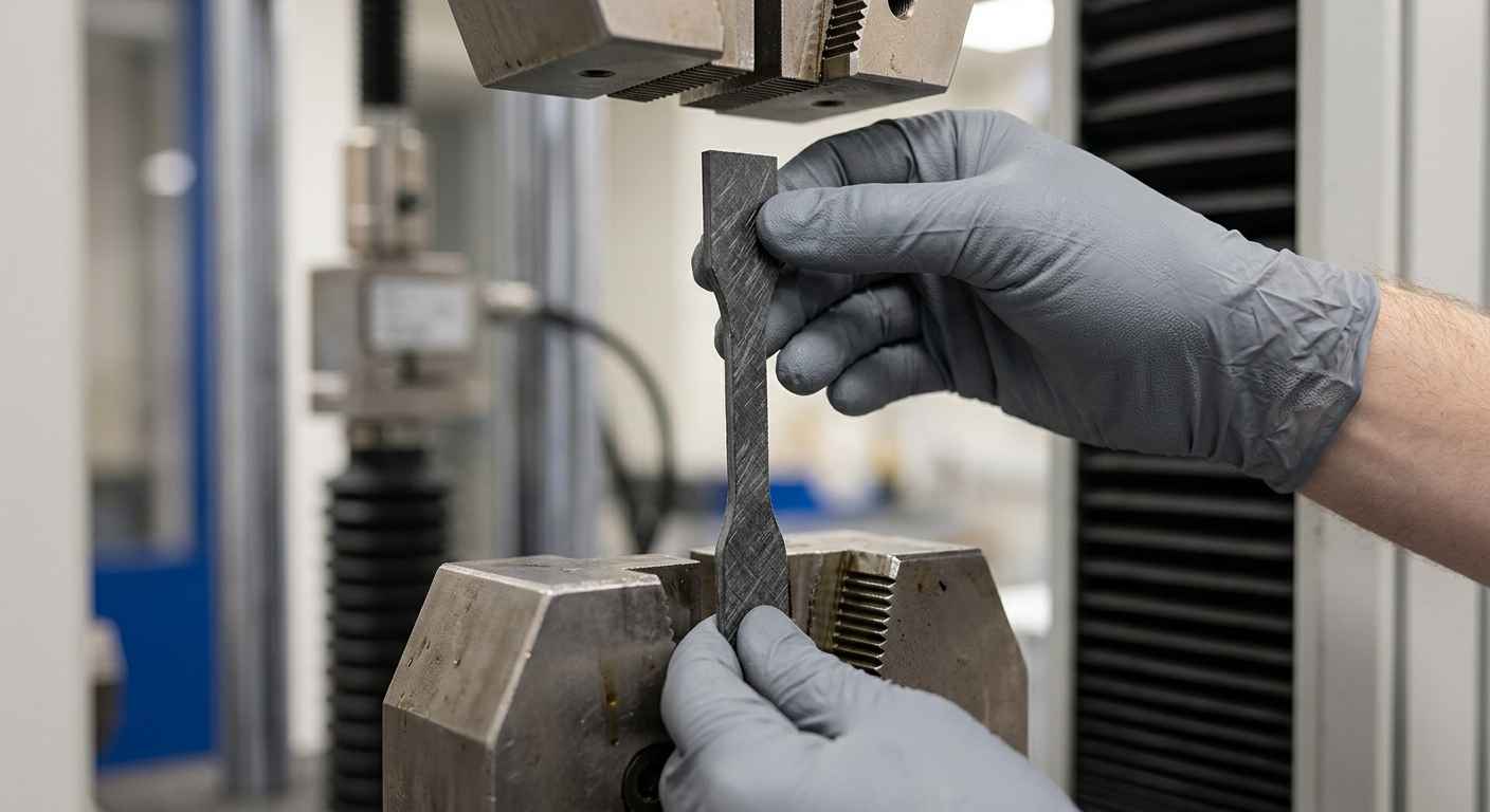
Mechanical validation starts with tensile properties to ISO 527, which give modulus, strength and elongation for the specific grade and fibre content, and continues with impact testing to check toughness at the lowest service temperature. Because filled polymers are anisotropic, the useful data come from specimens cut from the actual moulding in the loaded direction, not only from standard bars moulded under ideal conditions.
Thermal validation pairs heat deflection temperature (HDT, ISO 75) with the continuous service temperature and the coefficient of thermal expansion. Polymers expand several times more than metals, so a polymer part clamped or mated to a metal one can distort, loosen or bind across a temperature cycle. Quantifying expansion and HDT together tells you whether the assembly holds its fit and its form across the real operating range.
Creep, ageing and metal-versus-polymer differences
Creep testing under sustained load is the step that most often changes a decision, because it captures the slow deformation that no short tensile test reveals. A part under constant bolt preload or press-fit needs creep data at service temperature to predict whether it stays tight over years. Ageing and chemical resistance testing then confirm the polymer survives its fluids, UV, cleaning agents and thermal cycles without embrittlement, and fatigue testing checks cyclic load paths that a static number cannot cover.
The differences from metal are systematic and must all be checked: fibre-orientation anisotropy, strong temperature and time dependence of properties, and moisture absorption that plasticises polyamides and shifts stiffness and dimensions. The table below frames the criteria that decide a substitution and what each one demands before you commit.
| Criterion | Metal | Technical polymer | What to validate before substituting |
|---|---|---|---|
| Stiffness and modulus | High and isotropic (70 to 200 GPa) | Low and directional (2 to 20 GPa) | Modulus in the loaded direction; deflection under real geometry and ribbing |
| Service temperature | Stable over a wide range | Limited by HDT and continuous use rating | HDT to ISO 75 plus long-term continuous service temperature |
| Fatigue and creep | Defined endurance limit; negligible creep | No clean endurance limit; creeps under sustained load | Creep at service temperature and cyclic fatigue on a moulded part |
| Corrosion and chemical | Corrodes; may need coatings | No corrosion; chemical compatibility varies | Resistance to service fluids, cleaning agents, UV and thermal cycling |
| Weight and cost | Dense; multi-step manufacturing | Light; consolidated in one moulding shot | Part-cost model at volume including tooling and integrated functions |
| Function integration | Requires assembly of separate parts | Snap-fits, seals and bosses in one part | Tolerances, weld-line strength and dimensional stability of the integrated design |
Process effects and the mistakes that sink a substitution
The injection process sets the real properties of a polymer part, so a moulded component can behave very differently from the datasheet specimen. Weld lines, fibre orientation and wall thickness create local weaknesses that only appear in the finished geometry, and most failed substitutions trace back to ignoring them.
How the injection process shifts real properties
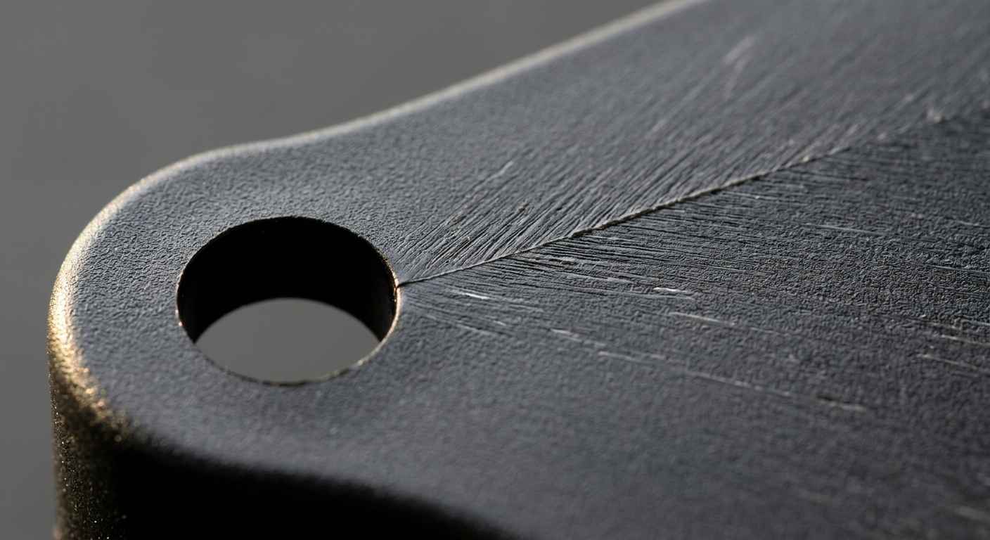
Weld lines form where two melt fronts meet around a hole or boss, and fibres do not bridge that seam, so strength there can drop well below the bulk value. Fibre orientation follows the flow, making the part directionally stiff and prone to warp as it cools unevenly. Wall thickness changes cooling rate and crystallinity, which shifts stiffness, shrinkage and dimensional accuracy across the same part. None of this shows up in a supplier’s tensile bar, which is moulded to favour clean, aligned, defect-free flow.
Datasheet properties come from an idealised specimen moulded under ideal conditions; your part has gates, weld lines and variable walls, so the only trustworthy numbers come from testing the actual moulded component.
Common mistakes when substituting a material
The most common mistake is trusting the datasheet as if it described the part. Datasheet values are ceilings measured on optimal specimens, and real components underperform them wherever geometry, weld lines or process variation intervene. The second mistake is ignoring creep and temperature dependence, validating only a room-temperature tensile test and missing the slow relaxation and softening that appear in service.
The third mistake is validating the wrong sample: testing a standard bar instead of a representative moulded part, or testing polyamide dry-as-moulded when it will run conditioned and moisture-plasticised in the field. Moisture alone can cut a polyamide’s stiffness and grow its dimensions enough to change a fit. Avoiding these three errors is less about caution than about testing the right thing, and it draws directly on how INFINITIA characterises lightweight materials for automotive applications, where the moulded part, not the resin, is the unit of truth.
Deciding a substitution on evidence, not optimism
A metal-to-polymer substitution earns its place when weight, cost, corrosion or part consolidation drive the redesign, the mechanical and thermal demand stays inside a measured margin, and the substitute is validated on a part that reflects the real injection process. Stiffness ceilings, high service temperature, creep, fatigue and conductivity mark the boundaries where a polymer stops being the right answer, and fibre orientation, temperature dependence and moisture uptake are the differences that a datasheet will never warn you about. The engineering polymer that wins is the one whose modulus in the loaded direction, HDT, creep response and aged chemical resistance were measured, not the one with the most attractive brochure.
If you are weighing a metal-to-polymer redesign, send the candidate grades, the part geometry and the real service conditions (loads, temperatures, fluids and duty cycle), and receive a validation plan with mechanical, thermal, creep and ageing tests run on representative moulded parts so the substitution decision rests on measured behaviour.
Frequently asked questions about material substitution
When does it make sense to replace a metal with a technical polymer?
Replacing a metal with a technical polymer makes sense when weight, cost, corrosion resistance or part consolidation drive the redesign and the mechanical and thermal demand stays within a measured margin. The strongest cases combine several drivers, such as a corrosion-free housing that also integrates seals, bosses and cable guides into one moulded part. It stops making sense when the component is stiffness-limited, runs hot for long periods, carries sustained or cyclic loads near the limit, or must conduct current.
What properties must you validate when substituting a material?
You must validate mechanical, thermal, creep, ageing and fatigue behaviour, measured on a part that represents the real injection process. Mechanical validation covers tensile properties to ISO 527, modulus in the loaded direction and impact toughness; thermal validation pairs heat deflection temperature (ISO 75) with continuous service temperature and thermal expansion. Creep under sustained load, chemical and UV ageing, and fatigue on cyclic paths complete the picture, because each captures a failure mode that a single room-temperature test would miss.
Can a polymer replace a structural metal?
A polymer can replace a structural metal only when the load case is strength-limited rather than stiffness-limited and the demand sits inside the validated envelope of a fibre-filled grade. Because an unfilled polymer’s modulus is roughly two orders of magnitude below steel’s, deflection-critical brackets and load paths near the material limit rarely survive a direct swap. Where the reinforcement is heavy, the part behaves like a composite, and the same characterisation logic used in structural composite work should govern the decision.
Why is the material datasheet not enough?
The material datasheet is not enough because its values come from idealised specimens moulded under optimal conditions, while your part has gates, weld lines and variable wall thickness that lower real performance. Datasheet numbers set a ceiling and help build the shortlist, but they overstate what a moulded component delivers wherever geometry or process intervene. They also usually report dry-as-moulded polyamide, ignoring the moisture the part will absorb in service, which shifts stiffness and dimensions.
How does the injection process affect the substitute’s properties?
The injection process sets the substitute’s real properties through fibre orientation, weld lines and wall-thickness effects that a datasheet specimen never shows. Fibres align with the melt flow, making the part directionally stiff and prone to warp; weld lines where melt fronts meet carry much lower strength because fibres do not bridge them; and wall thickness changes cooling rate, crystallinity and dimensional accuracy. Reliable numbers therefore come from testing the actual moulded part in the loaded direction, not a standard bar.