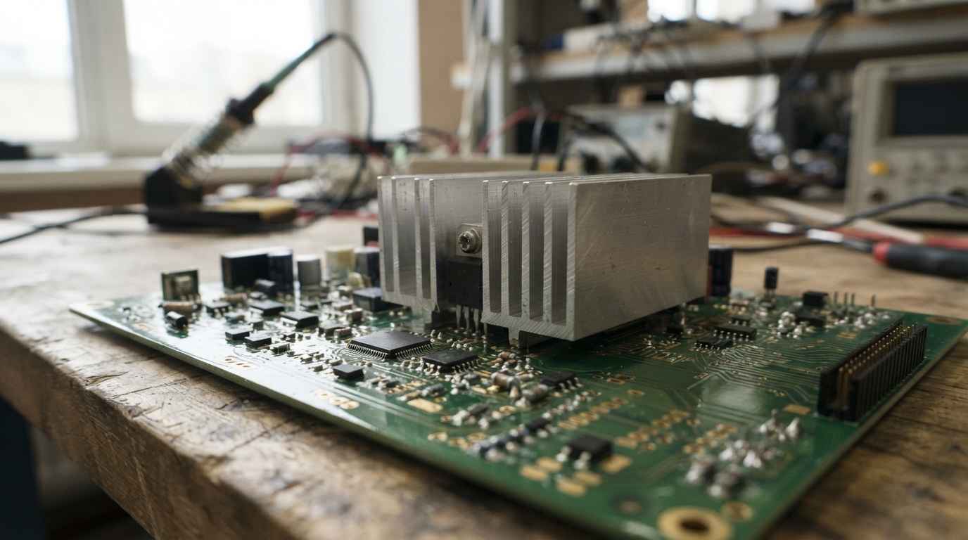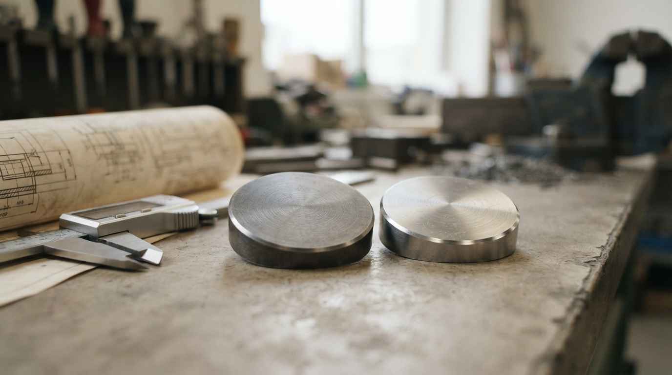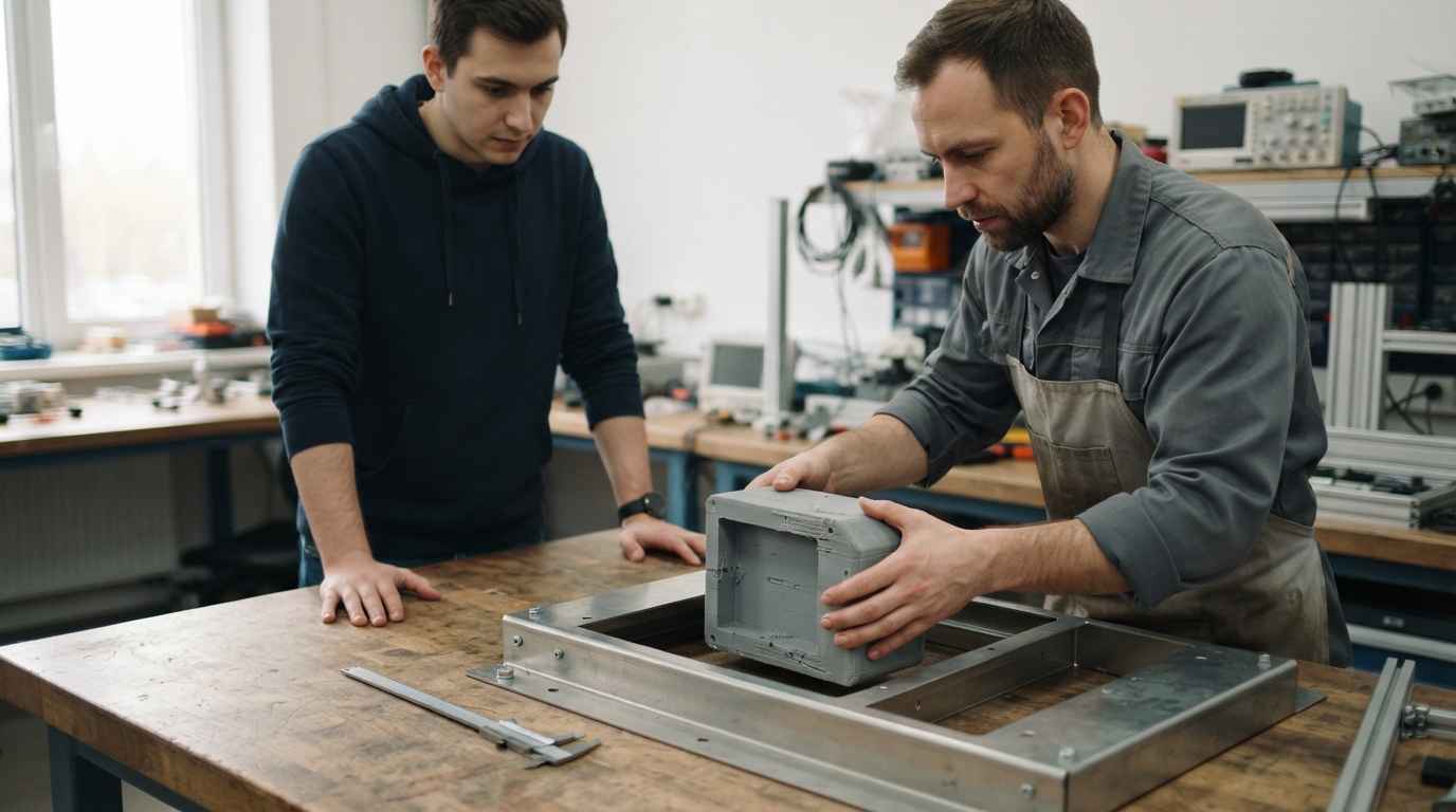

A low fidelity prototype is a physical representation of a product that reproduces its geometry and internal layout, but not its material or its manufacturing process. It answers questions about shape, fit and use, and it answers nothing about strength, service life or sealing.
The trouble does not start when the part comes out badly, it starts when it comes out well. A printed volume carrying the geometry of the final product drops into the space you reserved for it and takes a squeeze between your fingers, so it invites conclusions that sit outside its reach. The minimum viable prototype and the other levels of prototyping and prototype manufacturing exist because every question calls for a different part.
Assigning each question to a fidelity level is a product development decision, not a workshop detail. When the assignment goes wrong, the mistake never shows up on the prototype. It shows up months later, with the mould already cut and the real part behaving differently.
MINIMUM VIABLE PROTOTYPE
Have you approved a geometry on a mock-up and watched the real process contradict it? Take a look at our minimum viable prototype

What a low fidelity prototype is and which part of the piece is representative
A low fidelity prototype is representative in geometry and not representative in material, process or finish. That asymmetry is what makes it useful, because a mock-up that measures what the final part will measure answers everything that depends on dimensions and nothing that depends on microstructure.
Fidelity is not a single scale. A part can carry the exact geometry of the drawing, be built in a resin that appears nowhere on the bill of materials, and have its function reduced to a movement you push by hand. Geometry, material, process and function are raised separately, and each one costs a different amount of money.
Prototype fidelity is measured along separate axes, geometry, material, process and function, and a low fidelity prototype can be exact on the first and empty on the other three. Mistaking the axis you raised for the axis your decision depends on is where the error begins.
Faithful geometry and non-representative material in a low fidelity prototype
The geometry of a low fidelity prototype is usable as it stands, provided you know its real tolerance, which belongs to the process that built it and not to the drawing. A part printed by filament deposition carries a scatter of its own, with different shrinkage in the layer plane and in the build direction, so a two tenths interference may belong to the design or to the prototype, and only dimensional verification against the drawing tells the two apart.
Material is another matter. The tensile figures on a thermoplastic data sheet are obtained under the test conditions of ISO 527-2, which sets how tensile properties of moulding and extrusion plastics are determined on specimens of specified geometry, either moulded or machined to size. That condition of applicability is what blocks the transfer, because your prototype shares neither the specimen nor the process that produced the figure. Anisotropy adds to it, since a part built layer by layer has planes of weakness at the interfaces and the direction in which you break it settles the outcome before the design does. Whatever number comes out describes your printer, not your part.
Non-representative process, what a low fidelity prototype leaves out
The manufacturing process is what turns the geometry on the drawing into the geometry that exists, and a low fidelity prototype skips that step. In injection moulding, the process imposes minimum and even wall thicknesses, draft angles, gate position, weld lines where the flow meets itself, and shrinkage that is not the same in every direction. In sheet metal, the minimum bend radius and springback are in charge. The mock-up shows you the geometry you want, not the geometry the chosen process can give you.
Even with that limit, low fidelity decides well when the question is about volume and about how parts relate to each other. In a scale prototype built to present a product idea to investors, the question was whether the proposal held up as an object, and scale and shape are enough for that.
One step above sits the functional prototype, which already carries real function and sometimes production material. What that level validates and what it does not is worked through in what a functional prototype does and does not validate. The ground here is the step immediately below, low fidelity, and the criterion that tells you when to leave it behind.
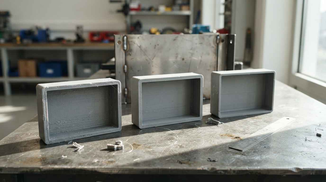
Which decisions a low fidelity prototype closes and which it leaves open
A low fidelity prototype closes decisions about architecture, overall volume, ergonomics, fit and coarse kinematics, and it leaves open everything that depends on how the material behaves. Both lists are short, and they are worth writing down before the part is made.
Architecture, volume and coarse kinematics, the decisions it does close
Product architecture is settled with pure geometry. How many pieces the assembly splits into, where the circuit board sits, where the cable enters and which component hits which other one when the lid closes are questions about occupied space, and the answer does not change once the material becomes the final one.
Overall volume works the same way. Whether the unit fits the nineteen inch rack, whether it goes into the shipping case with its foam, or whether a hand reaches the screw with the screwdriver fitted are measurements, and a dimensionally verified mock-up delivers them with the same authority as a production part. Ergonomics accepts low fidelity on one condition. Grip, reach and the clearance for a gloved hand depend on shape and distances rather than on material, and what makes the finding defensible is stating it against defined measurements instead of against an impression. ISO 7250-1 describes basic human body measurements and their anatomical landmarks for use in technological design, and it is what lets you assert that a grip circumference falls outside the intended range. It sets no acceptance criteria and holds no population data, which live in another standard of the same family.
Coarse kinematics comes in with the same caveat. A mock-up tells you whether the lid opens without hitting anything, how much sweep a lever needs and whether two mechanisms cross each other, and it does not tell you with what force or for how many cycles. In the design and prototyping of a coupling to improve how it is handled, that was exactly the kind of question on the table.
Screening concepts out is the application with the best ratio of cost to value. With three concepts on the table and three cheap mock-ups, the one that does not fit the available space falls away within a week. Ideation and concept generation gains more from three comparable rough mock-ups than from a single well finished one.
Strength, sealing and thermal behaviour, what low fidelity does not touch
No decision about mechanical strength can be taken on a low fidelity prototype, because the part breaks wherever the process that built the mock-up left it weak. A printed tab gives way at the interface between layers, and that failure mode belongs to the prototype. Fatigue life is just as far out of reach, since it depends on the material, the surface finish and the residual stresses of the real process.
Sealing is the clearest case. IEC 60529 classifies the degrees of protection provided by enclosures for electrical equipment through the IP code, with the first characteristic numeral covering the ingress of solid objects and the second covering water, for equipment of rated voltage not exceeding 72.5 kV. Its condition of applicability closes the door, because the degree is assigned after testing the enclosure as built, with its real gaskets and its real closing process, and a mock-up has neither of the two.
Thermal behaviour allows a partial answer that is best not stretched. The geometry of the airflow and the presence of a thermal short circuit between inlet and outlet can be studied on a mock-up with full validity. Steady state temperature cannot, because the conductivity and heat capacity of a prototype resin and of extruded aluminium are nothing alike.
Type approval closes the list. No test meant to support a declaration of conformity is run on a sample that is not representative of production, so a low fidelity prototype is only good there for preparing the test, checking that the part fits the laboratory fixture and fixing the measurement points.
| Project question | What the low fidelity prototype answers | What it takes to close it | What happens if you close it on low fidelity |
|---|---|---|---|
| Do all the parts fit the available volume? | Answers it in full | Nothing more, verified geometry is enough | Nothing, this is its home ground |
| Can a gloved hand reach the control? | Answers it through shape and distances | Nothing more if you make up the mass with ballast | Nothing, provided you record the ballast used |
| Does the clip survive the opening cycles? | Does not answer it | Production material and process | You drop a sound design or approve a poor one |
| Does the seal hold after thermal cycling? | Does not answer it | Real enclosure with its gaskets and closure | You reach approval without knowing if it seals |
| Does the lid deflect as the screws are tightened? | Hints at relative stiffness, gives no value | Material and wall thickness of the chosen process | You size the joint against a modulus that does not exist |
| Does the unit shed heat in steady state? | Answers the geometry of the airflow | Real material, wall thickness and power | You design the venting against a false conductivity |
| Does the assembly meet the applicable requirement? | Does not answer it | Sample representative of production | You repeat the test and lose the laboratory slot |
The first two rows are cheap and the next five are not, so the value of a low fidelity prototype lies in exhausting the first two before spending on the rest.
A low fidelity prototype does not give partial answers to material questions, it gives false answers that look like measurements. A printed clip that breaks after twenty cycles is not a pessimistic estimate of the moulded clip, it is a fact about the printer that made it.
TELL US ABOUT YOUR CASE
Not sure which question your current prototype can actually close? Send us the models and your list of open doubts and we will propose the minimum fidelity level that answers each one
The cost of mixing up the closed decisions with the open ones
Mixing up the two lists carries two costs, one from too much confidence and one from too much caution, and both are paid late. The first lets through a design that does not work, the second kills a design that did work, and the second is the one that leaves no trace.
Dropping a concept because of a prototype failure and not a design failure
The false negative is the hidden cost of low fidelity prototyping. An integrated hinge breaks along the layer plane on the printed mock-up, the concept is dropped at the design review and nobody looks at it again. That same hinge in moulded polypropylene, with the molecular orientation the flow gives it across the bending zone, is a proven solution. You have cut the good concept and carried on with the mediocre one.
What makes the problem chronic is that rejections are not documented as rigorously as approvals. An approved concept leaves minutes, a drawing and a purchase order, while a rejected concept leaves one line in a presentation. If that line says the hinge broke, without saying which material it broke in, the reason for the rejection stays confused with a technical result.
The same care applies to operating principles, which have their own route through the phases of a proof of concept. The practical difference is that a proof of concept can get away with any material when the principle is geometric or kinematic, and cannot get away with it when the principle rests on a material property.
Redesign after the tooling, where the false positive is paid
The false positive is paid in steel. If the geometry is approved on a mock-up and the real process contradicts it, the change arrives with the mould already cut, and there the modification has an awkward asymmetry, because taking steel away is straightforward and putting it back calls for inserts, weld build-up or a new block. A wall that turned out too thin is corrected by removing material from the mould, while a rib that has to be added to the part means new cavity.
The chain of consequences is the painful part. A tooling change drags along revalidation of the first parts, process parameter tuning, fresh dimensional verification and, if the component sat inside an approved assembly, repetition of the test that supported the declaration. The cost of the redesign is not the cost of the mould, it is the cost of the schedule that shifts behind it.
A geometry change costs hours in the three dimensional model, days in a mock-up and weeks in a mould that has already been cut. The fidelity level at which you decide fixes which of those three currencies you will pay the correction in.
When to raise the fidelity level and what to record before you do
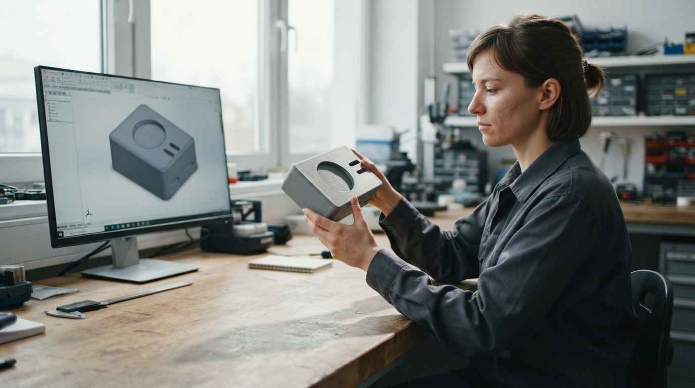
The moment to raise the fidelity level arrives when the pending decision depends on a variable the current prototype does not reproduce. It does not arrive by calendar or because budget has become available, but because there is a specific unanswered question and the axis it depends on is sitting low.
A criterion for raising the fidelity level without overpaying
The criterion has three steps and applies to each question separately. Write the pending question down, identify which axis the answer depends on, and raise that axis only. If the doubt is whether the clip retains, material and process go up and the geometry can stay rough. If the doubt is whether the assembly fits behind the dashboard, geometry is already high and nothing needs raising.
Raising all four axes at once multiplies the budget without buying information. A prototype that replicates material, process, geometry and full function costs what a pre-series costs, and it earns its place when the pending questions are spread across all four axes. When only one is left open, paying for four is buying three answers you already had.
There is a second criterion, which functions go into the first version of the product, and that is a scope decision rather than a fidelity decision. That discussion belongs to the minimum viable product and is better kept separate from fidelity, because the two are settled on different grounds, scope against the market and fidelity against the technical uncertainty still on the table.
What to record from a test on a low fidelity prototype
A test on a low fidelity prototype supports a decision only if what the prototype was not is put on record. The representativeness record has four entries, the material actually used with its trade designation, the process parameters that affect the resulting geometry, the dimensional verification against the drawing with the features that fell outside tolerance, and the known differences from the intended production part.
Above that goes the question, written as a question, with the criterion used to answer it and the answer obtained. Below it goes the explicit list of questions that test did not answer, and that entry is what makes the record defensible, because it shows the decision was taken within its reach rather than by oversight.
The physical side completes the set. Photographs of the part with a visible scale reference, the fixture used to hold it, the load or the gesture applied, and the part itself kept and labelled. When a production part fails, the first question that lands is what was validated and on what, and a record that states precisely what the prototype was not protects the decision better than a report that only says it worked.
Low fidelity is not a worse prototype, it is a smaller question
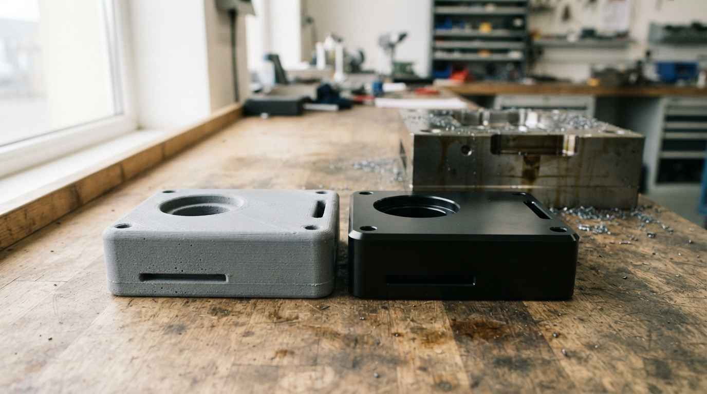
A low fidelity prototype is the right tool for everything decided through geometry and the wrong tool for everything decided through material. The difference between a development that moves forward and one that circles is whether each question was assigned to the fidelity level able to answer it.
Keeping both lists written down costs little and avoids the two expensive breakdowns of a project, the concept dropped because of a prototype failure and the tooling cut around a geometry the real process cannot deliver.
If you have several concepts on the table and you do not know which one deserves a representative part, send the three dimensional models, the list of questions you still have open and the environment the product has to fit, with its limiting dimensions. You will get back the assignment of each question to a fidelity level, which prototype it takes to close it, and the order in which they are worth building so that no decision is taken on a part that cannot answer it.
Frequently asked questions
How much is worth spending on a low fidelity prototype before moving up a level?
The sensible ceiling for a low fidelity prototype is the value of the decision it closes, and once you pass it you are buying fidelity you will not use. Finish is a practical signal, because if the quote includes sanding, paint or a metal insert for a part whose job is to check whether something fits, the money is paying for appearance rather than for an answer. Efficient spending at this level goes into the number of comparable variants and not into the quality of a single one, because the value comes out of the comparison. Once the next question on the list depends on material, extra money on the mock-up returns nothing and it is time to change level.
Is a low fidelity prototype any use for choosing between two manufacturing suppliers?
It is no use for choosing a supplier, because that choice rests on each shop’s process capability and dimensional control, and a low fidelity prototype exercises neither. It is useful for something adjacent, since it fixes the geometry and the envelope you quote against, so the offers you receive answer the same part and the price differences mean something. It also shows at quotation stage which supplier flags the manufacturability problems in your geometry, which is a reading of technical judgement. The firm choice comes later, with parts from the real process and their dimensional verification.
Can ergonomics be decided on a low fidelity prototype when the weight is not the real one?
The geometric side of ergonomics can be decided, meaning reach, grip, visibility and clearance, and the side that depends on mass cannot, meaning perceived effort, fatigue and how the object balances in the hand. The practical way round is to ballast the mock-up up to the target mass while respecting the position of the centre of gravity, and to record the ballast, after which the ergonomic finding travels to the final product. Without that adjustment, a hollow housing that feels comfortable for ten seconds can be uncomfortable after ten minutes with its batteries inside. If the product is handled repeatedly, cross the ballasted mock-up with user studies before freezing the shape.
What drives the cost of a test on a low fidelity prototype?
Four factors drive it, the number of geometric variants you want to compare, whether a fixture is needed to hold the part, whether dimensional verification against the drawing is included, and whether people from outside the team take part in the usability side. Material and machine hours are the smaller share of the budget at this level, unlike one step up. Adding a variant to a batch that is already scheduled costs little, so decide the number of variants before release rather than after. If you are unsure how many are worth building, a technical feasibility analysis shortens the list before anything is made.
How long does it take to go from a low fidelity prototype to a representative part?
The usual lead time runs from one to four weeks depending on the complexity of the part and the process you move up to, with an urgent route of 24 to 72 hours for critical cases. The typical split is short on adapting the three dimensional model to the rules of the chosen process, medium on manufacturing and short on verification, and what normally governs the calendar is the availability of the material in the form the process needs. Send the model and the question you want closed, and you will get the route with the minimum fidelity level that answers it and its lead time, with no intermediate levels that add nothing.