

Other Prototype Manufacturing Technologies
Prototype manufacturing technologies other than 3D printing make it possible to produce parts in the production material, build short runs without final tooling and handle cuts, joints or finishes that a printer cannot reproduce faithfully.
Within our product development service, we choose how to make each prototype based on what it has to prove. In prototyping we use CNC machining when the part needs the real material, casting in printed molds to obtain several units in elastomer or resin, printed mold inserts to inject the production thermoplastic, and laser processes for cutting, marking, micro-perforation and welding.
A printed prototype validates the shape, but its material and layered structure do not respond like the production part. A strength, flexibility or sealing test run on that part approves or rejects the design with data that do not always match production.
Talk to a specialist
Request a free initial consultation; contact a consultant from our team of specialists

What are prototype manufacturing technologies?
What is it?
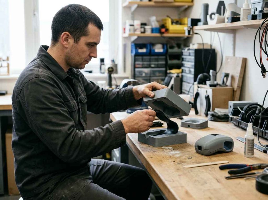
Prototyping techniques other than 3D printing are the processes used to produce a physical part when the material, the number of units or the finish of a printed part are not enough for validation. They include CNC machining, mold casting, injection molding with printed mold inserts and laser processes. Each one answers a different question: whether the part holds up in its real material, how an elastomer of a different hardness behaves or what defects the injection process introduces.
3D printing covers a large share of form and assembly validations, but it has well-known limits. A part built in layers is anisotropic, meaning its strength changes with direction, and printing materials only approximate production thermoplastics, metals and elastomers. When the prototype has to pass a mechanical test, a use test with flexible parts or a validation with the end customer, those differences affect the result and a different process is the better choice.
To choose the process we look at four variables: the material the part needs, the number of units, the required tolerance and finish, and the time available until the decision. CNC machining starts from a block of the final material; casting reproduces the part in elastomer or resin from a mold; injection with printed inserts uses the real process with rapid tooling; and laser processes cut, mark, perforate or join without contact.
Prototype manufacturing at INFINITIA
We start from the question the prototype has to answer and from its CAD model or drawings. With them we choose the process, the material and the number of units, and we review the design so it can be produced with that technique: tool-accessible radii, draft angles on cast or injected parts and uniform wall thickness.
To obtain several units in elastomer or resin we design casting molds, often printed, and cast the chosen material into them. That was the approach in product development with printed molds to cast elastomers of different hardness, where use tests made it possible to choose the right hardness.
When validation depends on the injection process, we produce mold inserts by DLP 3D printing in a high-temperature resin. In low-cost injection mold manufacturing through 3D printing, test specimens injected with the printed insert showed properties and finish very similar to those from a conventional mold.
We deliver the manufactured parts with the rationale for the process choice and, when the project requires it, the results of their dimensional inspection or of functional and mechanical tests. That information shows which parts of the design are validated and which still depend on the production process.
Benefits of prototyping with the right material and process
Benefits
It allows testing the prototype with data that hold for production. A part machined in the final material or injected with the production thermoplastic responds to load, temperature and use much like the final part, and the test result can be used to approve or correct the design.
It reduces risk before investing in tooling. Testing critical elements separately, such as joints, clips or stressed areas, allows their geometry to be corrected in CAD. In the redesign of an incubator to reduce manufacturing costs, the joining systems were machined and tested in isolation before the demonstrator was built.
It allows materials to be compared with the same geometry. Several identical parts cast in elastomers of different hardness, or injected in different grades of the same polymer, isolate the material variable and make it easier to choose through use tests or measurements in addition to the datasheet.
It brings the prototype closer to the first production runs. A casting mold or a printed insert produces a short run of consistent parts for user tests, internal validations or customer samples, without the cost or lead time of a steel mold.
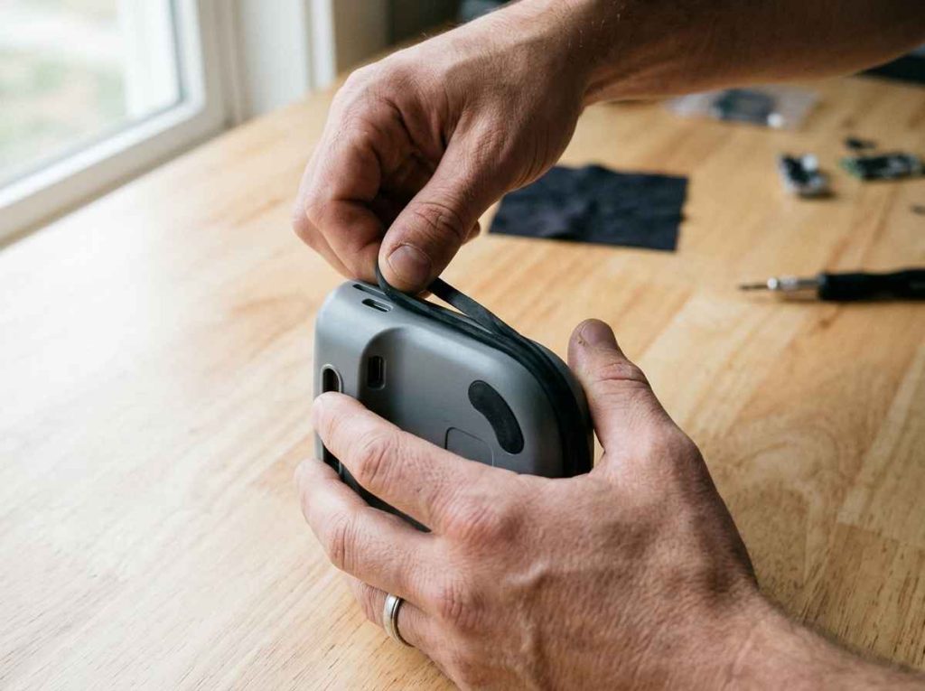
Prototype manufacturing techniques beyond 3D printing
Types
Each technique sets its own conditions for material, tolerance, finish and cost per unit. Machining, casting and injection produce three-dimensional parts with different fidelity to the production material and process; laser processes work on sheets, surfaces and joints.
We choose the technique based on the question the prototype has to answer and the number of parts, and we often combine several in the same assembly. 3D printing remains part of the process as the basis for molds and inserts and for parts that only validate form.
CNC machining of prototypes in production material
CNC machining produces the part by removing material from a solid block with a cutting tool guided by numerical control. It starts from the final material, whether aluminum, stainless steel or an engineering plastic, so the part keeps its mechanical properties, heat resistance and behavior against moisture or chemicals. Its limit is tool access: deep cavities, undercuts and very small internal radii make the part more expensive or impossible to machine.
It is the option for mechanical tests, bolted joints, parts exposed to temperature and metal components of a functional prototype, as well as fixtures and test supports. If the final design will be injection molded, the machined part does not reproduce weld lines or molding stresses.
Elastomer and resin casting in molds
Casting consists of pouring a liquid material, such as an elastomer or a resin, into a mold that reproduces the part geometry and removing the part once the material has cured. The mold can be printed from the CAD model, which reduces its cost and lead time. One mold yields several identical parts, and the Shore hardness, the scale used to measure elastomer hardness, can be changed from one batch to the next.
It is the technique for seals, bellows, grips and flexible parts that have to be tested in use, because a part printed in layers does not reproduce the response of a cast elastomer. It also provides rigid samples without going through injection molding. Printed molds are produced with the same 3D printing we use throughout prototyping.
Injection molding with printed mold inserts
A printed mold insert is the part of the mold that shapes the part, produced by DLP 3D printing in a high-temperature resin and mounted in an injection mold base. It allows the production thermoplastic to be injected with the real process, so the part shows weld lines, sink marks (depressions in thick areas) or warpage that machining and casting do not anticipate. In return, the insert withstands fewer cycles than a metal mold.
| Criterion | CNC machining | Mold casting | Printed insert |
|---|---|---|---|
| Material | Production grade | Elastomer or resin | Production grade |
| Production process | No | No | Yes |
| Tooling | None | Casting mold | Mold insert |
| Cost per part | High | Medium | Low |
| Typical use | Mechanical test | Flexible parts | Process validation |
It is the way to validate the production material and process in a short run before ordering the final mold. The table summarizes how the three techniques in this group differ; the choice depends on whether the test needs the real material, the real process or both.
Laser cutting of films and sheets
Laser cutting separates material along a programmed path, without contact or a physical tool, using a beam that melts or vaporizes the cut zone. It is applied to polymer sheets, multilayer films and printed circuit boards, which are used to make flat gaskets, membranes, front panels and templates. Adjusting power, speed and pulse frequency prevents burning or delaminating the most sensitive materials, especially films with layers of different composition.
It allows flat parts to be iterated without die-cutting tooling and shows whether a material can be cut without damage before the production process is defined. When the final part will be die cut, the laser-cut prototype reproduces the geometry, although its edge does not look the same as a die-cut edge.
Laser micro-perforation and marking for finishes
Laser micro-perforation opens micrometer-scale holes with very short light pulses that remove material without contact, and laser marking modifies the surface to engrave permanent text, codes or textures. On metals, polymers or wood they make it possible to obtain backlighting through perforations that are nearly invisible when the light is off, illuminated symbols and wear-resistant traceability marks.
In a prototype they are used to validate finishes and graphics that a render cannot demonstrate, such as the intensity of backlighting or the legibility of an engraved symbol. They complement appearance prototypes when the design includes technical surfaces, and they allow process parameters to be set before transferring them to the production supplier.
Laser welding of polymers
Laser welding of polymers joins two plastic parts in a lap joint: the beam passes through the laser-transparent part and heats the interface, the contact surface with the absorbing part, until both surfaces melt locally. To choose the laser and its parameters, the optical properties of the materials are characterized beforehand by Vis-NIR spectroscopy, and joint quality is assessed with tensile tests and microscope inspection of its cross-section.
It makes it possible to check whether two materials can be joined without adhesives or screws, and with what strength, before designing the assembly line. It is used in sealed housings, sensors and devices where the joint has to be clean and leave no visible marks on the outside.
Sectors where prototyping with production material and process adds the most value
Sectors
These techniques add the most value where the prototype has to be tested in the real material: injection-molded plastic parts, elastomer components, housings joined without screws and metal parts under load.
In sectors with type approvals, health regulations or user testing, a test on a part that does not behave like the production part means repeating validations when the final mold arrives.
Prototype manufacturing technologies in automotive: plastic parts, seals and brackets
In automotive and mobility, plastic components, elastomer seals and metal brackets have to pass vibration, temperature and aging tests before type approval, and the prototype material conditions the result.
- Injection-molded parts: clips, covers and brackets in the production polymer for assembly, vibration and breakage tests.
- Seals and bellows: elastomers cast in several hardness grades to check sealing and travel.
- Metal brackets: parts machined in aluminum or steel for load and fatigue tests on the assembly.
A prototype with the right material and process reaches validation tests with results that hold when production tooling is built.
Prototype manufacturing technologies in electronics: housings, front panels and sealed joints
In electrical and electronic equipment, the housing protects boards and connectors, often has to reach an ingress protection rating and usually includes front panels with indicators, push buttons or backlit areas that are part of the interface.
- Sealed joints: laser welding of plastic housings without adhesives or visible screws, followed by strength testing of the joint.
- Front panels and membranes: laser cutting of multilayer films for membrane keypads, flat gaskets and insulation between components.
- Backlighting: laser micro-perforation and marking of symbols that are only visible when the device is on.
Combining laser processes with injected or machined parts makes it possible to validate sealing, interface and assembly of the device in a single prototype before ordering the housing molds.
Prototype manufacturing technologies in medical devices: elastomers and clean joints
In medical devices and laboratory equipment, the parts in contact with the patient or user are usually elastomers or engineering plastics, and joints have to be clean, with no burrs or gaps where dirt can collect.
- Flexible parts: grips, valves and caps cast in different hardness grades for use tests with healthcare professionals.
- Adhesive-free joints: laser welding of polymers in housings and disposable cartridges, with no glue residue in the joint area.
- Representative material: parts injected in the intended polymer for cleaning and use tests.
Making the prototype with the intended material and joint allows tests with professionals and preliminary trials to be carried out on parts representative of the final device.
Prototype manufacturing technologies in consumer goods: feel, finish and first units
In household appliances, housewares and small devices, the product is judged by its feel, its finish and its resistance to daily use, and the first units are needed for user tests and sales presentations.
- Feel: elastomer grips and coatings cast with the hardness to be validated in the hand and in use.
- Finishes: laser marking and micro-perforation of symbols, textures and illuminated areas on front panels and controls.
- First units: cast or injected parts in short runs for user panels and in-home tests.
Short runs in representative material make it possible to gather feedback on use and durability before committing the investment in production molds.
Prototype manufacturing technologies in machinery: load-bearing parts, brackets and traceability
In machinery and capital equipment, prototypes are often metal parts under load, brackets, guides and fixtures that have to be mounted on the real machine and work with its actual loads and clearances.
- Load-bearing parts: components machined in the intended metal for strength, wear and fit tests.
- Integration: machined brackets and adapters to add a new function to existing machines.
- Traceability: laser marking of codes and references on metal and plastic parts, resistant to wear and cleaning.
Making load-bearing parts in the production material allows the modified machine to be tested under real conditions without waiting for all its parts to be manufactured in their final form.
Prototype manufacturing technologies in plastics and rubber: injection process and formulation
In plastics and rubber processing, part behavior depends on both the material and the process: mold temperature, injection pressure, elastomer curing or gate location.
- Real process: injection with printed inserts to anticipate sink marks, weld lines and warpage before the steel mold.
- Formulation: casting of elastomers in different hardness grades with the same part geometry to compare their response.
- Grade comparison: test specimens and parts injected in several polymer grades for mechanical testing.
A printed insert makes it possible to test the geometry, material and injection conditions of a new part in a short run before ordering the final mold.
The prototype manufacturing process as part of validation
Value
How a prototype is made determines what data can be drawn from it. A test on a part with the right material and process gives results that hold in production, while a test on the wrong part means repeating validations when the final mold arrives.
We plan the process choice together with the prototype test plan. First we define what has to be proven (strength, sealing, feel or injection behavior), then we choose the technique that achieves it at the lowest cost, using criteria like those in the article on prototyping technologies by tolerance and lead time. This avoids making the same part twice and reserves the production material and process for the parts whose results depend on them.
Combining techniques in the same prototype keeps costs in check: 3D printing for parts that only validate form, machining for those that carry load, and casting or injection for those that need the production material. When tests confirm the design and the project needs first production runs, the next step is the design of complex tools and spare parts to produce with repeatability. In regulated sectors, that path documents which material and process each part was validated with.
If you have a design ready for prototyping and are unsure which process to use, send us the CAD model or drawings, the intended production material, the number of units you need and the tests the prototype has to pass. We will propose the right technology or combination of technologies, with lead time and budget, and deliver the manufactured parts along with the rationale for the process choice.
Frequently asked questions about prototype manufacturing technologies
FAQs
What is the difference between a machined part and an injected part in the same material?
Even with the same polymer, the machined part comes from a block with a more uniform internal structure, while the injected part has chains oriented along the flow, weld lines where two material fronts meet and residual stresses from cooling. These differences change strength, deformation and failure mode.
That is why a machined part validates geometry, fits and material behavior well, but not the defects specific to molding. If the test depends on them, such as a clip breaking at a weld line, the part needs to be injected, even if only with rapid tooling.
How does a printed insert differ from a bridge mold?
Both allow injection with the real process before the production mold, but they differ in material, service life and cost. The printed insert is made of high-temperature resin, is produced quickly and is intended for short validation runs; the bridge mold is aluminum or soft steel tooling that is machined and withstands runs of thousands of parts.
The printed insert fits when the geometry may still change and the goal is to test the process with little risk. The bridge mold makes sense when the design is frozen and parts are needed to launch the product while the final mold is being built.
What materials can be cast in a prototype mold?
Mainly liquid elastomers and resins that cure at room temperature or with mild heating, such as silicones and polyurethanes. Elastomers are chosen by hardness, from very soft for seals and grips to firm for bumpers and dampers, and resins reproduce rigid parts with a look and feel close to those of a plastic.
The Shore hardness scale allows elastomers from different manufacturers to be compared on a common basis. Several hardness grades can be cast in the same mold, although the cast part does not reproduce all the properties of a vulcanized rubber or an injected thermoplastic.
Which parts are not suited to CNC machining?
Parts with very thin walls, deep narrow cavities, internal undercuts or internal radii smaller than the available tool are poor candidates, because they require several setups or special tools, or cannot be produced at all. The same applies to parts that only need to validate form, where machine time is not worthwhile compared with printing.
In those cases the part can be split into machinable sections and joined, cast instead, or redesigned if the geometry is not functional. Opening up an internal radius or relaxing a dimension that does not affect use usually saves operations without changing what the part has to do.
How is a design prepared for machining, casting or injection?
The CAD model is reviewed against the rules of each process. For machining, tool access, internal radii and setups are checked; for casting or injection, draft angles, uniform wall thickness, parting line location and areas where material can become trapped or sink as it cools.
This review applies the design for manufacturing criteria of the production part to the prototype, so what is learned while making it carries over to the final mold. If the design does not yet include them, we propose the changes before manufacturing.
What tests can be run on these prototypes?
Machined, cast or injected parts can undergo mechanical tests such as tensile, flexural or impact testing, fatigue and accelerated aging tests, sealing tests and dimensional inspection by 3D scanning against the CAD model. The validity of the result depends on the part having the production material and, when it matters, the production process.
It is effective to define the tests before choosing the technology, because they determine the material and the number of parts. A fatigue test needs several identical specimens, and a use test needs several units that can be handled without breaking.
How is the prototype material chosen if the production material has not been decided?
First, a short list of candidates is drawn up based on service conditions (temperature, loads, chemical exposure), target cost and the intended production process, as described in material and manufacturing process selection. Prototypes are then made with those candidates.
If the production material is not available in block or castable form, a substitute is chosen with similar properties in what the test measures. In that case we document which results will need to be confirmed with the final material once the mold exists.
How many parts can a casting mold or a printed insert produce?
It depends on the material, the geometry and how much the mold is stressed during demolding. A well-designed casting mold can produce dozens of consistent parts, and a printed insert withstands a short run of shots before wear or temperature affects finish or dimensions.
For longer runs, a second mold or insert is made, which costs less than the first because the design is already done, or the project moves to a bridge mold. Setting the number of parts needed from the start allows the right option to be chosen and avoids hitting the limit halfway through the run.
How much does a prototype made with these technologies cost?
Cost depends on the process, the material, the size and complexity of the part, the number of units and the required tolerances and finishes. In machining, machine time and the number of setups weigh most; in casting and injection, the design and manufacture of the mold or insert, which is spread across the parts produced.
To give you a firm figure we need the 3D model, the intended material and the number of parts. Send us that information and we will prepare a proposal with the recommended technology and, if there are several reasonable options, a comparison of their cost and lead time.
How long does it take to get the parts?
Typical lead times range from one to four weeks depending on the technology, part complexity and number of units. Machining a simple part and laser cutting are the most direct processes; casting and injection add the design and manufacture of the mold or insert and its trials before the run.
If you need the parts for a test or a presentation with a set date, tell us at the outset. With it we plan the manufacturing sequence and tell you what scope is realistic in that time, for example bringing forward critical parts and leaving those that only validate form for later.
What do I need to send to get started?
Send us the 3D model in a standard CAD format, such as STEP, and drawings with critical dimensions and tolerances if you have them. Specify the intended production material, the number of parts, the final manufacturing process if already decided and what you will use the prototype for (mechanical test, use test, presentation or process validation).
If the prototype has to be assembled with other existing parts or components, include their models or send us a sample. With that information we will propose the technology and confirm lead time and budget before manufacturing.
What should I do if I don’t know which technology my prototype needs?
Tell us what you want to check with the prototype and what stage the design is at. From there we will propose the technology, or combination of technologies, that answers that question at the lowest cost, and explain what you will be able to validate with it and what will remain pending for production.
If the design is not yet frozen, the usual approach is to start with printed prototypes to fix the form and reserve machining, casting or injection for when testing with the production material or process is needed.