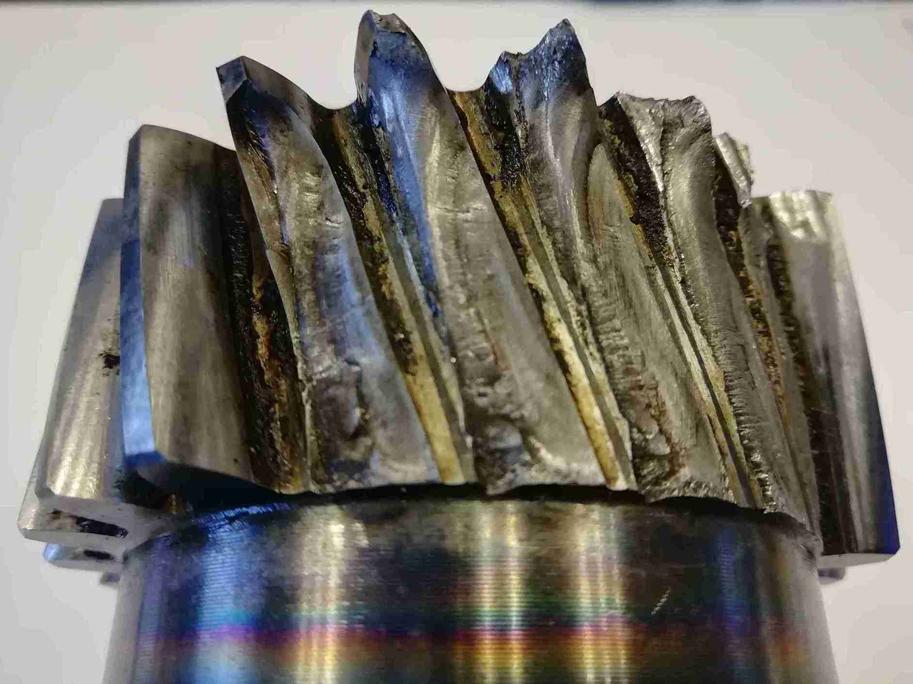

Fatigue fracture is identified by three distinct zones on the fracture surface: the initiation point (smooth, localized area), the propagation region with concentric beach marks visible to the naked eye, and the final fracture zone (rough, with a brittle or ductile appearance). Confirmation is carried out through fractography and SEM electron microscopy testing, which reveals the fatigue striations characteristic of this mechanism.
What is fatigue fracture and why is it relevant?
Fatigue fracture is one of the most common failure mechanisms in components subjected to repeated loading over time. Unlike overload failure, where rupture occurs immediately after exceeding a critical threshold, fatigue damage accumulates progressively, even under relatively low stress levels. This behavior makes it a particularly critical phenomenon from an industrial perspective, as it can develop without visible signs until advanced stages.
In many mechanical systems, cyclic loads are inherent to their operation: vibrations, rotations, pressure pulses, or thermal variations generate fluctuating stress states that promote this type of degradation. As a result, components that appear to operate within their design limits may fail after a certain number of cycles, making prediction difficult without appropriate models or data.
Fatigue fracture is silent: damage remains invisible until advanced stages, making it the failure mechanism with the greatest potential for causing unplanned downtime in industrial environments.
Furthermore, the progressive nature of fatigue means that final failure is often sudden. This has direct implications for safety and operability, especially in sectors such as automotive, energy, or industrial machinery, where unexpected failure can lead to significant damage or service interruptions.
Correctly identifying this mechanism is also essential to avoid misdiagnosis. In some cases, fatigue fracture can be mistaken for brittle or overload failure if the evidence is not properly analyzed, leading to incorrect solutions and recurrence of the problem.
Crack initiation and growth mechanisms in fatigue fracture
From a technical standpoint, fatigue fracture begins with crack initiation in localized areas where stress concentrations exist. These areas may be associated with geometric discontinuities, surface defects, or microstructural heterogeneities in the material. Initiation is not always immediate and may require a significant number of cycles before the crack becomes detectable.
Once initiated, the crack enters a stable propagation phase, growing progressively with each load cycle. This growth is not uniform and depends on factors such as stress amplitude, loading frequency, and environmental conditions. During this phase, localized deformations promote crack front advance.
Finally, when the remaining load-bearing section is insufficient to withstand the applied load, final fracture occurs, usually suddenly. This last event is often the only visible one, which can lead to incorrect interpretations if the full damage history is not considered.
This process is closely related to fatigue life, which represents the number of cycles required to reach failure, and to the evolution of cumulative damage in the material.
Factors influencing fatigue causes in industrial materials
The causes of material fatigue cannot be attributed to a single factor, but rather to the interaction of multiple variables affecting both crack initiation and propagation. Among the most relevant are stress concentrators, which generate significant local increases in the stress state.
Surface conditions play a critical role. Processes such as machining, heat treatment, or corrosion can introduce defects that act as crack initiation sites. Even minor surface irregularities can significantly reduce a component’s fatigue resistance.
The operating environment also has a direct influence. The presence of corrosive agents, humidity, or elevated temperatures can accelerate damage mechanisms through processes such as corrosion fatigue or oxidation. In these cases, the interaction between mechanical and chemical phenomena increases the complexity of the problem.
Finally, material properties such as microstructure, grain size, or the presence of inclusions condition behavior under cyclic loading. In industrial applications, the combination of these factors with mechanical failures due to cyclic loads makes fatigue a highly context-dependent phenomenon.

Effects of fatigue fracture on system reliability
Fatigue in industrial components has a significant impact on system and equipment reliability. Its cumulative and progressive nature means that damage can develop over long periods without detection, increasing the risk of unexpected in-service failures.
From an economic standpoint, such failures can generate high costs associated with production downtime, component replacement, and efficiency loss. In highly demanding sectors, even minor interruptions can have relevant consequences in terms of productivity.
Mechanical failures due to cyclic loading can develop without visible signs until final fracture, compromising both system safety and production continuity.
Furthermore, fatigue does not only affect individual components but can compromise the overall behavior of the system. Degradation of one element may alter load distribution, generating overloads in other parts and accelerating chain damage processes.
Another relevant aspect is the difficulty of early detection. Unlike other failure mechanisms, fatigue does not always present clear signs until advanced stages, making specific inspection and monitoring techniques necessary.
Influence of cyclic loading on component failure
Mechanical failures due to cyclic loading occur across a wide range of industrial applications, from structural components to elements subjected to continuous vibration. In many cases, these failures occur at critical design areas where stresses are highest. This is the type of problem addressed in projects such as the failure analysis of metal parts to resolve fractures in industrial assembly, where identifying the failure mechanism was decisive in preventing recurrence.
Operationally, the occurrence of such failures typically results in unplanned maintenance interventions. This not only increases costs but also reduces equipment availability and affects production planning.
Additionally, fatigue failure of a component can have indirect consequences. For example, fragment release or loss of functionality may damage other components or create hazardous situations.
From a technical perspective, these failures highlight the need to properly account for cyclic loads during the design phase and to implement condition-based maintenance strategies.
Role of fatigue testing in material design and validation
Material fatigue testing is a fundamental tool for evaluating component behavior under repeated loading. These tests provide experimental data that serve as a basis for design and validation.
The interpretation of results draws on established technical references in the sector, including ASTM and ISO standards specific to fatigue testing and fracture surface analysis. These references provide a structured framework for the analysis, define common terminology, and enable comparison of results across materials, treatments, or service conditions — which is particularly relevant when findings need to be presented to third parties or used as the basis for technical decision-making.
Through these tests it is possible to determine the relationship between stress amplitude and cycles to failure, typically represented by S-N curves. This information enables the establishment of design limits and appropriate safety factors.
Fatigue testing also enables comparison between different materials or surface treatments, supporting the selection of more fatigue-resistant solutions. Its application extends beyond the design phase to improvement and optimization processes.
In industrial environments, these tests are complemented by in-service analysis, allowing validation of whether real component behavior matches theoretical expectations.

Fatigue fracture diagnosis methods
Identifying a fatigue fracture requires a structured approach combining macroscopic observation, microscopic analysis, and evaluation of service conditions. This process enables differentiation of fatigue from other failure mechanisms and supports evidence-based conclusions.
Fracture surface analysis is one of the most relevant tools in this process. Interpreting the patterns present on the surface provides direct insight into the origin and evolution of damage. However, observation alone may be insufficient. It is necessary to integrate this information with data on design, material, and operating conditions to achieve a complete understanding of the problem.
Fracture surface analysis, combined with load history and service conditions, allows reconstruction of failure origin with a high degree of reliability.
Additionally, considering the component’s load history and in-service traceability is critical. Lack of this information may lead to incomplete or incorrect interpretations, especially in systems where real conditions differ from design assumptions. Analysis should therefore incorporate operational, maintenance, and anomaly data whenever possible, enabling correlation between physical evidence and actual service context.
Identification of fatigue fracture surfaces and characteristic patterns
Fatigue fracture surfaces exhibit distinctive features that allow identification of this failure mechanism. At the macroscopic level, different zones corresponding to the stages of fracture are typically observed.
One of the most representative features is beach marks, which appear as concentric or semicircular bands reflecting the progression of the crack front over time. These marks are often visible to the naked eye or under low magnification.
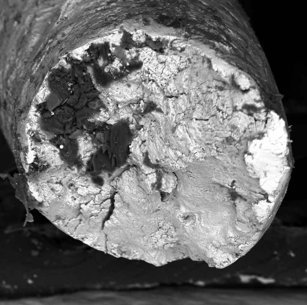
At the microscopic level, fatigue striations are key evidence. These striations represent the incremental advance of the crack with each load cycle and provide strong confirmation of the fatigue mechanism.
Correct interpretation of these patterns is essential to avoid diagnostic errors, particularly in cases where multiple failure mechanisms coexist.
Differences between fatigue fracture, brittle fracture, and overload fracture
The following table summarises the distinctive characteristics of the three most common fracture mechanisms in industrial metal components. Correctly differentiating between them is the first step in directing the analysis towards the actual causes of failure:
| Characteristic | Fatigue fracture | Brittle fracture | Overload fracture |
|---|---|---|---|
| Load type | Cyclic, repetitive | Single, sudden load or at low temperature | Single load exceeding the strength limit |
| Visible plastic deformation | Minimal or none | None | Present in ductile materials |
| Surface appearance | Smooth in propagation zone, rough at final fracture | Smooth, crystalline, with cleavage facets | Rough, with cup-and-cone in ductile materials |
| Beach marks | Present (visible to the naked eye) | Absent | Absent |
| Microscopic striations (SEM) | Present and periodic | Absent | Absent |
| Identifiable initiation point | Yes, localised at stress concentrator | Not always | Not always |
| Propagation rate | Slow and progressive | Very fast (instantaneous) | Instantaneous upon exceeding the limit |
| Most common sectors | Automotive, machinery, energy, aeronautics | Steels at low temperature, castings | Accidental overload events |
Analysis of fatigue crack propagation in real industrial contexts
The failure mode study of fatigue crack propagation enables reconstruction of damage evolution and understanding of the conditions that led to failure. Analyzing crack growth direction, rate, and trajectory variations provides key insights into component behavior in service.
In industrial applications, this analysis is complemented by evaluating applied loads, environmental conditions, and material characteristics. This integration enables identification not only of the failure mechanism but also of its underlying causes.
Identifying the failure mechanism is only the first step: without determining the root cause — material defect, stress concentrator, unforeseen service condition — the problem has a high probability of recurring.
When fatigue fracture recurs in production, identifying the mechanism in isolation is not sufficient. A systematic approach is needed, as explained in our article on how to identify the root cause of a repetitive production failure and resolve it definitively.
Analyzing crack growth rates can also provide quantitative insights, particularly when correlated with theoretical models or experimental data. This allows estimation of the component’s life stage at the time of failure, as well as assessment of whether crack growth was accelerated by unforeseen external factors such as overload events or aggressive environmental conditions.
Understanding fatigue failure in materials
Fatigue fracture is a complex phenomenon resulting from the interaction between cyclic loads, material properties, and service conditions. Its progressive and silent nature makes it a particularly critical failure mechanism in industrial environments.
Identifying this type of fracture requires detailed analysis combining fracture surface observation, study of characteristic patterns, and evaluation of the operational context. Features such as beach marks and microscopic striations are key evidence for diagnosis.
From a technical perspective, understanding this phenomenon enables not only failure identification but also its anticipation. Integrating experimental data, material analysis, and service condition evaluation is essential to improve system reliability.
In cases where fatigue indicators are detected or diagnostic validation is required, a root cause failure diagnosis conducted under a structured methodology goes beyond identifying the mechanism to determine why the crack initiated. Where the analysis needs to support litigation or a claim, we produce a technical report with full case documentation, which the designated expert can use as the basis for their formal expert opinion. For further information or a technical consultation, please visit our contact page.
Frequently asked questions about fatigue fracture
How is fatigue fracture distinguished from overload fracture?
Fatigue fracture shows a fracture surface with distinct zones: a smooth propagation region with concentric beach marks and a sudden, rough final fracture zone. Overload fracture, by contrast, shows a more uniform surface without these zones and, in ductile materials, visible plastic deformation. SEM electron microscopy confirms the mechanism: fatigue striations are exclusive to fatigue failure.
Which technique most reliably confirms fatigue fracture?
Scanning electron microscopy (SEM) with fatigue striation analysis is the most conclusive technique. At Infinitia we complement this analysis with EDX when necessary to rule out surface contamination, corrosion, or material composition anomalies as contributing factors to the failure.
When is a technical failure analysis report required in litigation or a claim?
When a fracture leads to litigation between manufacturer and customer, a supplier claim for a defective component, or a product liability process, having a rigorous technical report is a common prerequisite. At Infinitia we produce technical reports documenting the failure mechanism, root cause, and evidence obtained during the analysis. This documentation can be used by a forensic expert to support their expert opinion before third parties.
Does fatigue fracture affect metals and plastics in the same way?
No. In metals, fatigue produces well-defined microscopic striations and visible beach marks. In polymers and composites, the mechanism differs: matrix cracking fronts, delaminations, or crazing appear, requiring different analysis techniques. The diagnostic approach must be adapted to the material type and applied loading mode.