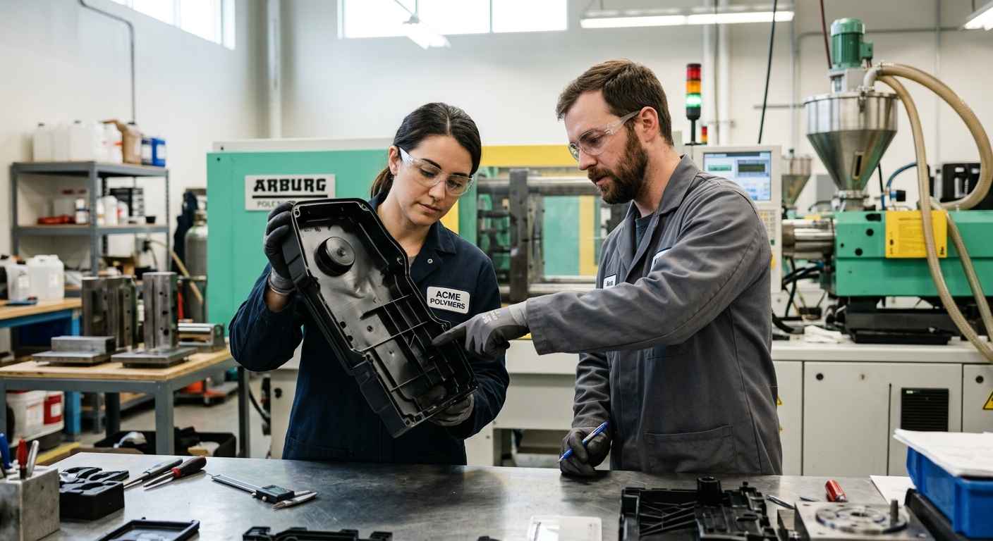

Injection molding defects are anomalies of the moulded part (sink marks, weld lines, warpage, flash, burn marks) caused by the material, the process or the mould, and they trigger batch rejection when a dimension, a surface or a mechanical property falls outside specification. You avoid them by controlling the process parameters, drying the resin and correcting part and mould design, and you confirm the fix with material and mechanical tests.
Every one of these anomalies is a symptom, not a root cause, and reading it correctly is what separates a one-off scrap event from a recurring quality loss. When a moulder ships a batch that a customer returns for short shots or a weak seam, the money is already spent: raw material, machine time, packaging and logistics. Treating plastic injection defects as an engineering problem rather than a cosmetic nuisance is central to technological innovation in polymer processing, and it connects directly to product improvement, where the geometry, the resin grade and the tool are revised together instead of chasing settings on the machine.
PRODUCT IMPROVEMENT
Do your injection-moulded parts come out with moulding defects? Discover our product improvement service

What injection molding defects are and why they appear
An injection molding defect is a deviation of the finished part from its dimensional, surface or structural specification that originates during the moulding cycle. Most of these anomalies are not random: they are the measurable fingerprint of one disturbed phase, and that reproducibility is exactly what lets you trace a defect back to its cause instead of guessing.
The four cycle phases where a defect starts
The moulding cycle has four decisive phases. In plasticising the pellets are melted and homogenised in the barrel, and this is where moisture and thermal degradation are carried in. In filling the melt is injected into the cavity at high speed, and a badly tuned speed profile produces jetting and flow lines. In packing the holding pressure compensates for the volumetric shrinkage of the cooling polymer, and its shortfall leaves sink marks and voids. In cooling the part solidifies and takes its final shape, and an uneven thermal balance sows warpage. A disturbance in any of these phases leaves a recognisable fingerprint on the finished part. The phases are not independent, either: an irregular plasticising step changes the melt viscosity and carries the problem forward into filling and packing, so a defect that shows up on cooling may have been created two phases earlier. Effective diagnosis therefore does not stop at the phase where the defect appears; it works back to the phase where it was generated.
Material, process and mould: separating the three origins
Behind every visible symptom there are three families of origin, and most persistent problems combine more than one. The material contributes through its grade, its viscosity and, above all, its moisture content: hygroscopic polymers such as polyamide, polycarbonate and PET absorb water from the air, and if the pellets are not dried the water flashes to steam in the barrel and produces splay, bubbles and a measurable drop in mechanical strength. The process contributes through melt and mould temperature, injection speed, holding pressure and cooling time. The mould contributes through gate location and size, runner balance, venting and cooling-channel layout.
This is why parameter tables alone rarely close a recurring defect. The interaction between resin behaviour, tool geometry and machine settings means the diagnosis has to move between disciplines, characterising the material with the same rigour applied to the testing of plastics and polymers before any parameter is touched. A grade change from the supplier, a regrind ratio that crept up on the shop floor or a filler that settled differently in a new lot can all shift the process window without a single knob being turned.
The same visible symptom can have opposite causes: a sink mark may come from insufficient holding pressure or from a wall that is simply too thick for the resin to pack, and only distinguishing the two prevents you from correcting the wrong variable.
The most common defects and their root cause
Each recurring defect points to a specific phase of the cycle, and naming the mechanism is the first step toward a stable correction. A single symptom can still answer to several combined causes, so reading the pattern correctly is what lets you fix the right place instead of compensating with settings that degrade another zone of the part.
The visual signature of each defect
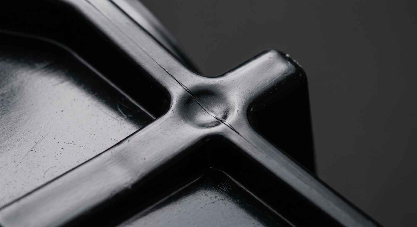
Sink marks are surface depressions over thick sections, ribs or bosses, where the core cools more slowly than the skin and the volumetric contraction is not compensated during packing. Weld lines (also called knit lines) form where two melt fronts meet after flowing around a hole, an insert or a second gate; the polymer chains do not fully interdiffuse across the interface, so the seam is both a visible line and a plane of reduced strength. Warpage is a dimensional distortion caused by differential shrinkage, typically from uneven wall thickness, asymmetric cooling or fibre orientation in reinforced grades.
Flash is excess material squeezed into the parting line or around inserts when clamp force, injection pressure or venting is out of balance. Burn marks (the diesel effect) are dark discolorations where air trapped in the cavity is compressed and ignites at the last area to fill, a venting problem more than a temperature one. Jetting leaves a snake-like mark from the gate when a fast melt stream enters an open cavity without contacting the wall. Bubbles and voids are gas pockets, either from moisture and volatiles or from vacuum voids formed as thick sections shrink internally. Flow lines are visual streaks that trace the fill pattern when the melt cools unevenly.
| Defect | Appearance | Typical root cause | How to correct it |
|---|---|---|---|
| Sink marks | Surface depressions over ribs, bosses and thick walls | Insufficient packing, wall too thick, short cooling | Raise holding pressure and time, reduce nominal wall, core out thick sections |
| Weld lines | Visible seam where two flow fronts meet, weaker in that plane | Melt fronts too cold, poor gate placement, low pressure | Increase melt and mould temperature, relocate the gate, add venting at the meeting point |
| Warpage | Twisting or bowing away from nominal geometry | Differential shrinkage, uneven cooling, fibre orientation | Balance cooling channels, uniform wall thickness, revise gate and packing profile |
| Flash | Thin fins of material at the parting line or inserts | Low clamp force, excess pressure, worn or misaligned tool | Raise clamp force, lower injection pressure, service the parting line |
| Burn marks | Dark or brown discoloration at the last area to fill | Trapped air ignited by compression, poor venting | Add or clean vents, reduce injection speed near end of fill |
| Bubbles and voids | Internal gas pockets or surface splay | Moisture in the resin, volatiles, internal vacuum in thick sections | Dry the pellets correctly, raise packing, reduce wall thickness |
Cosmetic versus structural defects
Cosmetic and structural defects call for different responses. A faint sink mark may be tolerable in a hidden area, while a weld line in a load-bearing zone compromises the service life of the part. The classification is not decoration: it decides whether a batch is accepted under concession or rejected outright, which is why the criterion should be fixed before the first defect appears rather than improvised in front of a doubtful part. Reinforced and pigmented grades add their own signatures, which is why lot-to-lot consistency of fillers and additives matters as much as the base polymer; drift in the characterization of additives and fillers can move shrinkage and flow enough to open a defect that the settings alone never caused.
TELL US ABOUT YOUR CASE
Do you have an injection-moulded part with recurring defects? Send us your case and we will propose a diagnosis of the defect and its correction
How to avoid batch rejection
Preventing rejection means fixing the process window, not chasing symptoms one shot at a time. Correcting with settings alone is tempting because it is fast, but when the problem lives in the design or the material, that adjustment hides the symptom and pushes the defect into another zone of the part.
Parameter control and the process window
The first lever is parameter control: define and lock a validated set of melt temperature, mould temperature, injection speed profile, holding pressure and cooling time, and record the process capability so that drift is visible before it produces scrap. A process running near the edge of its window will reject a batch the day a resin lot or an ambient condition shifts slightly. Material drying belongs here too: hygroscopic resins must reach the moisture level the datasheet specifies before they enter the barrel, using a desiccant dryer sized for the throughput and verified with a moisture measurement rather than assumed from a timer. Undried polyamide or PET will splay and lose strength no matter how well the machine is set, and the damage from hydrolytic chain scission in polyester and polycarbonate is not recovered by later drying. The process window is a range, not a single point, and its width depends on the polymer: an amorphous grade tolerates more deviation than a semi-crystalline one, whose shrinkage depends heavily on the cooling profile. Recording the centre of that window together with its limits also separates a slow process drift, which warns you with a trend, from an abrupt jump caused by a new lot or a change in ambient conditions, which appears without notice.
Part and mould design
The second lever is part and mould design. Uniform wall thickness, generous radii, ribs kept to roughly 60 percent of the adjacent wall, gates placed to push weld lines into non-critical zones and vents cut where air would otherwise be trapped remove whole categories of defect at the source. Getting the tool right the first time is an engineering exercise in its own right, as shown in the design and manufacture of a molding tool for a plastic component, where cavity, cooling and venting are resolved before steel is cut. When the choice is between a metal and a polymer part, the substitution decision itself changes which defects you will fight, a trade-off covered in the analysis of when to replace a metal with a technical polymer.
Most weld-line and warpage problems are designed into the part long before the first shot: wall-thickness transitions, rib proportions and gate location decide how the melt fills and cools, and changing them is cheaper than compensating on the machine forever.
The incoming and release control plan
The third lever is a control plan with incoming and release testing. Checking each resin lot for melt flow rate and moisture on receipt catches out-of-spec pellets before they are moulded, and validating first-off parts against dimensional and mechanical acceptance criteria confirms the batch complies. That control plan closes the loop between the process window and the finished part, so a rejection is anticipated on the line and at incoming inspection rather than discovered by the customer.
How defects are diagnosed and validated
Diagnosis begins with the material, because a large share of recurring defects trace back to the resin rather than the machine. Confirming that the polymer received matches the qualified grade, and that its moisture content was in range at the moment of moulding, rules a whole family of failures in or out at a stroke: splay, bubbles and hydrolytic degradation.
Melt flow rate and material control
Melt flow rate, measured to ISO 1133, quantifies the flowability of the melt and reveals whether a lot has degraded, been contaminated with regrind or simply differs from the qualified grade; a shifted MFR reshapes the process window and explains short shots, flash or weld-line weakness that settings cannot cure. Comparing the MFR of the incoming material against the reference is a fast check that avoids moulding a lot condemned in advance, and because it is quick it fits well as the first filter at incoming inspection, before machine time is spent on a doubtful resin. It is best read together with the regrind content: a slightly high MFR often betrays too much reincorporated grind, which not only flows differently but carries a thermal history that lowers the toughness of the finished part even when every dimension is within tolerance.
Mechanical testing at the weld line
Mechanical characterisation turns a visible line into a quantified risk. Tensile testing to ISO 527, run on specimens that contain the weld line and on reference specimens without it, gives the strength retention across the seam and tells you whether the knit is cosmetic or structural. That loss of properties is what decides whether the part will carry its service load or fail prematurely. Impact testing and, for the target application, evaluation of behaviour under load complete the picture where the part sees shock or fatigue, and these mechanical results are what convert an argument about appearance into an acceptance decision.
Chemical analysis, moisture and microscopy
Chemical and thermal analysis identify contamination, wrong grade, excessive regrind or thermal degradation in the barrel, while microscopy and inspection map porosity, filler distribution and the internal structure of a weld line or void. The chemical side is central to the chemical analysis of plastics and polymers that supports the decision. Microscopy also measures the real layer thickness in multi-component parts and pinpoints the exact interface where a delamination or debond starts, something external inspection cannot see. Combining resin characterisation, mechanical testing and microstructural evidence is what allowed the failure analysis and evaluation of polycarbonate injection conditions to separate a material issue from a processing one and point the correction at the right variable. That report then becomes a baseline: when the same defect returns months later, comparing the new part against the earlier characterisation shortens the diagnosis from days to hours.
From a recurring defect to a batch that passes first time
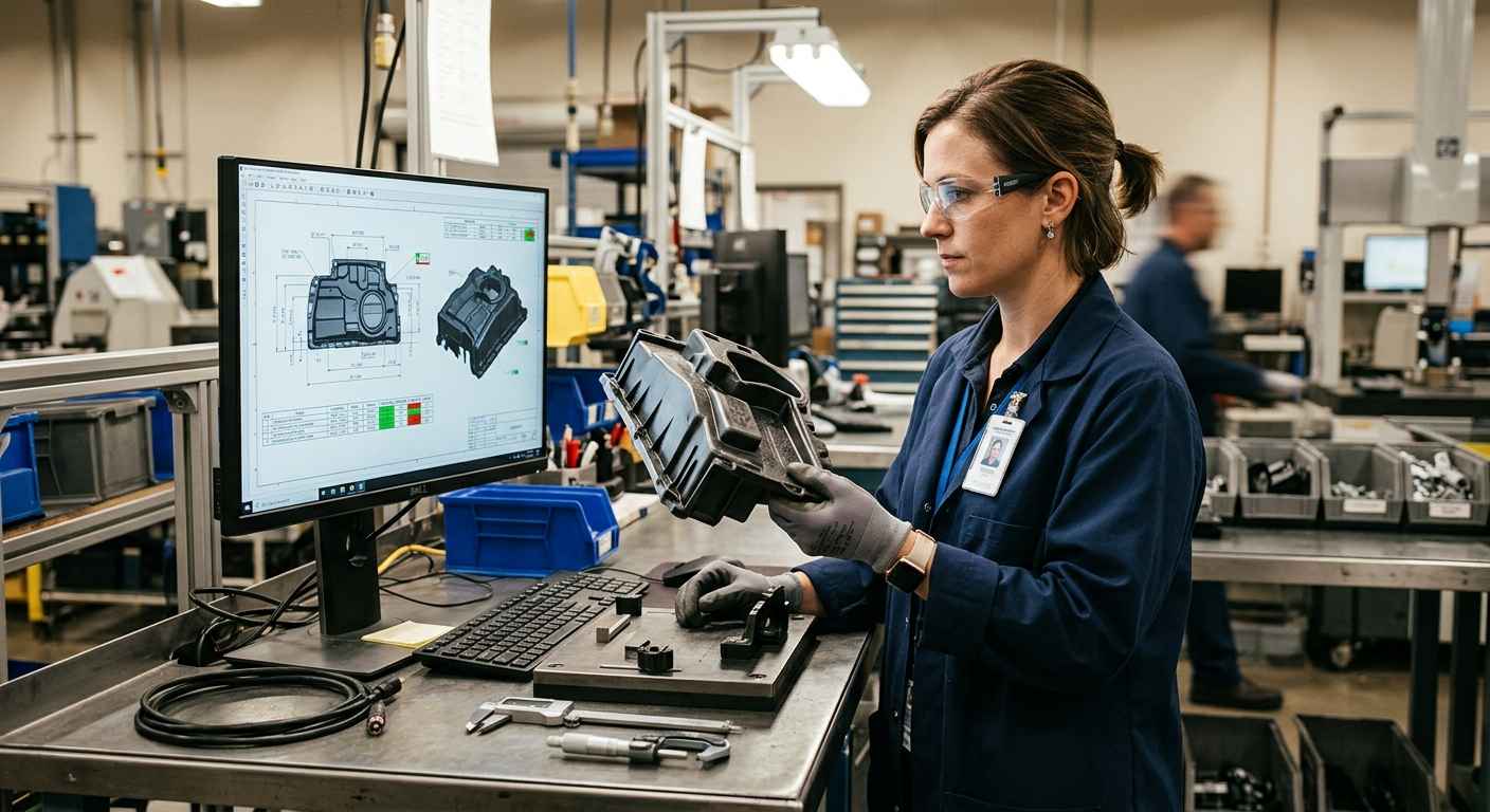
Injection molding defects stop being random once you treat them as signals of a specific phase of the cycle and a specific origin in the material, the process or the mould. Sink marks send you to packing and wall thickness, weld lines to melt temperature and gate location, warpage to cooling balance and shrinkage, splay and voids to drying and resin condition. Controlling the parameters holds the process inside its window, drying protects the resin, and part and mould design remove defects at the source instead of compensating for them shot after shot. The confirmation comes from measurement: melt flow rate and moisture on the material, tensile and impact strength across the critical section, and microscopy on the internal structure.
That is the difference between a batch that scrapes through inspection and one that passes first time, lot after lot, because the root cause was identified and closed rather than masked. Send your rejected parts, the resin datasheet and the current process sheet, and get back a root-cause diagnosis with the material and mechanical data that pinpoint whether the fix belongs in the resin, the settings or the tool.
Frequently asked questions about injection molding defects
What are injection molding defects?
Injection molding defects are deviations of a moulded part from its dimensional, surface or structural specification, caused during the moulding cycle by the material, the process or the mould. The most common are sink marks, weld lines, warpage, flash, burn marks, jetting and voids. Each one points to a specific phase (filling, packing or cooling) and to an origin that has to be identified before the correct fix can be applied, rather than treated as a purely cosmetic issue.
Why do sink marks occur?
Sink marks occur because a thick section, rib or boss cools more slowly at its core than at its skin, and the volumetric contraction of the cooling polymer is not compensated during the packing phase. The direct causes are insufficient holding pressure or time, a wall that is too thick for the resin, or premature gate freeze. You reduce them by raising and extending packing, coring out heavy sections and keeping wall thickness uniform, so the material solidifies evenly.
What is a weld line and why does it weaken the part?
A weld line is the seam that forms where two melt fronts meet after flowing around a hole, an insert or a second gate. It weakens the part because the polymer chains do not fully interdiffuse across the interface when the fronts are too cold, leaving a plane of reduced strength and, in reinforced grades, unfavourable fibre orientation. Tensile testing to ISO 527 on specimens that contain the weld line quantifies how much strength is retained and whether the seam is cosmetic or structural.
How do you prevent warpage in a moulded part?
You prevent warpage by minimising differential shrinkage across the part. Balance the cooling channels so both halves of the tool extract heat evenly, keep wall thickness uniform, and set a packing profile that avoids over-packing near the gate. In fibre-reinforced grades, gate placement controls fibre orientation and therefore the direction of distortion. Where geometry cannot be made uniform, flow and warp simulation before cutting steel identifies the distortion so the tool and gating can be corrected in advance.
How do you avoid rejection of a moulded batch?
You avoid rejection by fixing the process window instead of reacting shot by shot: lock validated parameters and monitor process capability, dry hygroscopic resins to the specified moisture level, and remove defects at the design stage through uniform walls, correct gating and adequate venting. A control plan that checks melt flow rate and moisture on each incoming lot and validates first-off parts against dimensional and mechanical criteria catches the variation that would otherwise reach the customer as a rejected batch.