
What was the challenge or problem to solve?
A company working with collaborative robots needed a custom design and manufacturing solution. It wanted to set up a test rig in which several cameras had to observe the process from different points. The setup it had did not cover that need: some components required modifications to improve their fit and certain functions remained unresolved due to the absence of specific parts. Without those parts, the tests could not be carried out under representative conditions.
INFINITIA was involved throughout the whole process, from data capture at the client’s premises to the assembly and testing of the mounts on their own setup. The challenge was not merely to draw a few parts, but to design versatile mounts, able to vary the camera position, in line with the timeframe and cost defined beforehand by the client.
Incomplete test setup: the limitations the client detected
A test setup is the set of physical elements (mounts, tooling, fixtures, sensors and capture equipment) assembled to reproduce specific usage conditions and record the real behaviour of a product or a process. The client already had a working setup, but had detected a series of limitations that prevented it from being validated.
Those limitations were of two kinds. On one hand, some existing components required modifications to improve their fit within the assembly. On the other, certain functions planned for the setup were unresolved, simply because specific parts that did not yet exist were missing.
The distinction between the two problems shapes all the subsequent work. Adjusting an existing component is, in essence, a dimensional correction on something already defined. Covering a missing function requires designing a new part from scratch, with its own requirements for fixing, rigidity, accessibility and assembly. Separating the two fronts from the outset makes it possible to size the real effort of the project and set priorities.
An incomplete experimental setup not only delays the schedule: it also compromises data reliability. If a camera is not firmly held or does not always point at the same spot, the images stop being comparable between tests and the conclusions lose value. This kind of need is addressed through custom test setups and tailored testing, the usual route when off-the-shelf machinery does not cover the required configuration.
Camera mounts with fixed and variable position
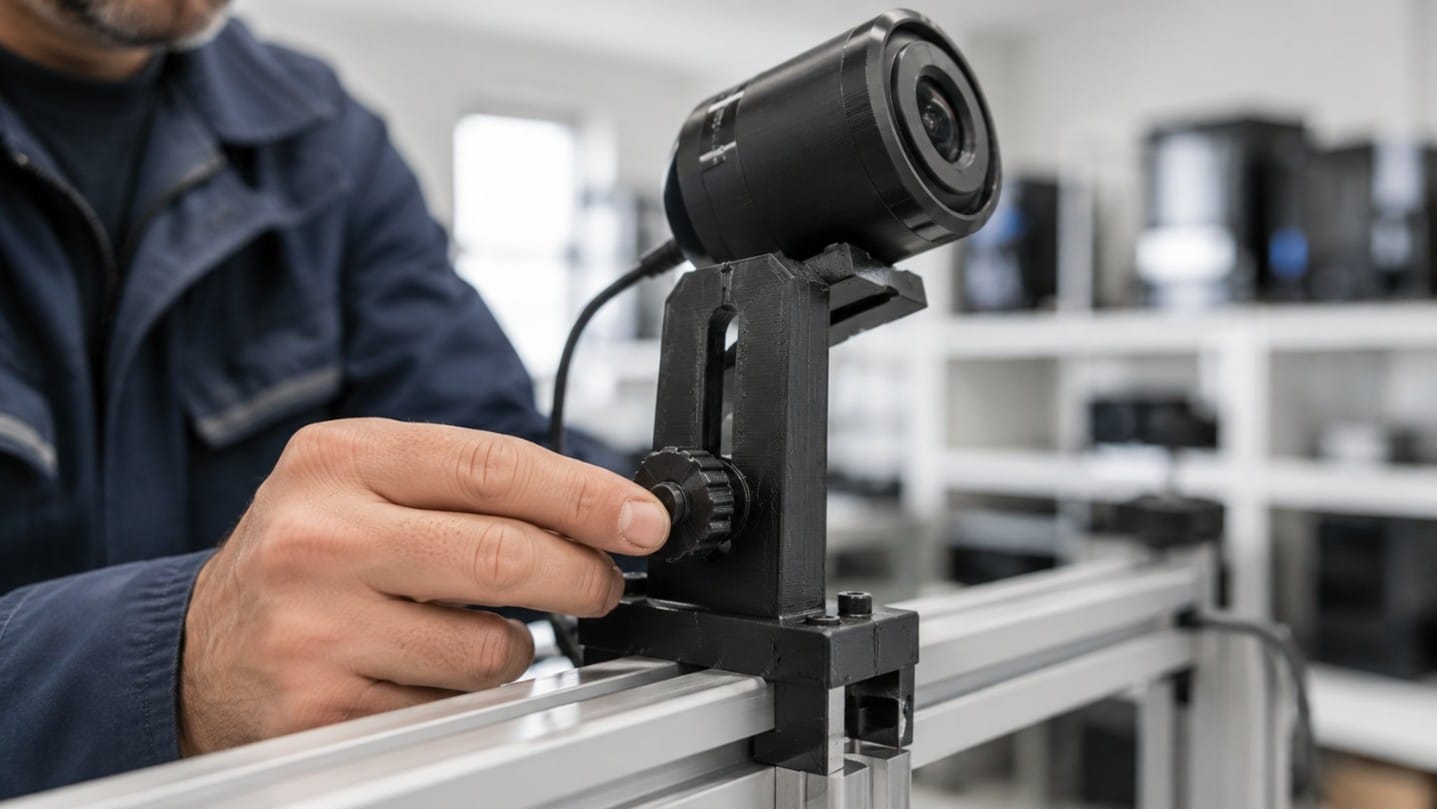
The mechanical solution had to include a series of camera mounts, some fixed-position and some variable-position. These are not two versions of the same part, but two distinct functions within the same setup, and each imposes different design requirements.
A fixed-position mount keeps the camera always at the same point and with the same orientation, which ensures the repeatability of the captures test after test. A variable-position mount allows the height, angle or framing to be modified, something essential when it is still being explored from where it is best to observe the process. The former prioritises rigidity; the latter, the ability to adjust without losing stability.
A collaborative robot (cobot) is a robot conceived to share a workspace with people. In these environments, cameras perform observation, control and process-verification functions, so their position directly determines the quality of the information obtained.
Combining fixed-position and variable-position mounts in the same setup ensures the repeatability of the captures without giving up the ability to adjust the viewpoint during the tests.

On top of this there was a starting condition: the assembly had to be stable and validated under real conditions, not merely correct on paper. A poorly held camera introduces vibrations, displacements and blurring that get confused with the phenomenon being measured, so mechanical integration was part of the expected result from the very first moment.
Design of versatile tooling with limited time and cost
The challenge for INFINITIA focused on the design of tooling that was versatile. A jig is an auxiliary device that holds, positions or guides an element during a process, and here it had to meet three conditions at once: allow the camera position to vary, resolve the pending adjustments of the setup, and do so within a limited timeframe and at a contained cost.
Versatility was not an aesthetic extra, but a technical requirement. A mount that allows adjustments avoids redesigning the assembly every time a test condition changes, and anticipates process variations that are not yet fixed at that stage. When the setup is still being defined, the parts’ margin of adjustment is what avoids repeating work.
Time and cost are not external constraints on the design: they directly condition the manufacturing technology chosen and, with it, the admissible geometry of each part. Designing without keeping in mind how the mount will be manufactured leads to parts that are correct on screen and unviable in the workshop. This balance between function, manufacturing and budget is the core of the design of complex tools and spare parts, where the part is conceived for a real production process and a real deadline.
There was also an integration requirement: the mounts were not installed on an empty bench, but on an already-assembled setup, with its own anchors, travels and clearances. Each new part had to coexist with what was already there, respecting the robot’s movement and the operator’s access.
How was it addressed or what was the solution?
The Product Development team laid out a path of chained phases, in which each step reduced the uncertainty of the next: first getting to know the real setup on site, then modelling the necessary parts in CAD and, finally, manufacturing, assembling and testing them in their definitive location.
That order explains the result. Taking the setup information into the digital model before manufacturing anything, and then validating the parts in their real location, is what makes it possible to work with agility without giving up technical rigour. Manufacturing was resolved through prototyping and prototype manufacturing, the route that turns a design into a physical, functional element in very short timeframes.
On-site measurement: the starting point of the design
The first task was to get in touch with the client to understand their needs. The team travelled to their premises to see what the current setup was like and gather the information needed to carry out the project. That close contact provides a global view of the process that is hard to obtain remotely.
On that same visit, the measurements needed to start designing the tooling were taken. On-site measurement is what anchors the design to reality: dimensions of the existing anchors, distances between elements, space available for each camera, and travels that must remain clear.
A setup in service rarely matches its documentation in detail. Checking it in situ avoids the most expensive error of the project, which is discovering an interference when the part is already manufactured. Measuring before modelling reduces the number of iterations and shortens the total time, precisely the scarcest resource in this assignment.
Seeing the process in operation also provides information that does not appear in any measurement: how the operator works, which areas they need to reach, from where it makes sense to observe the operation, and what variations are foreseeable. That reading of the context is what turns a vague requirement into a usable technical specification.
3D CAD modelling to ensure the mount adapts
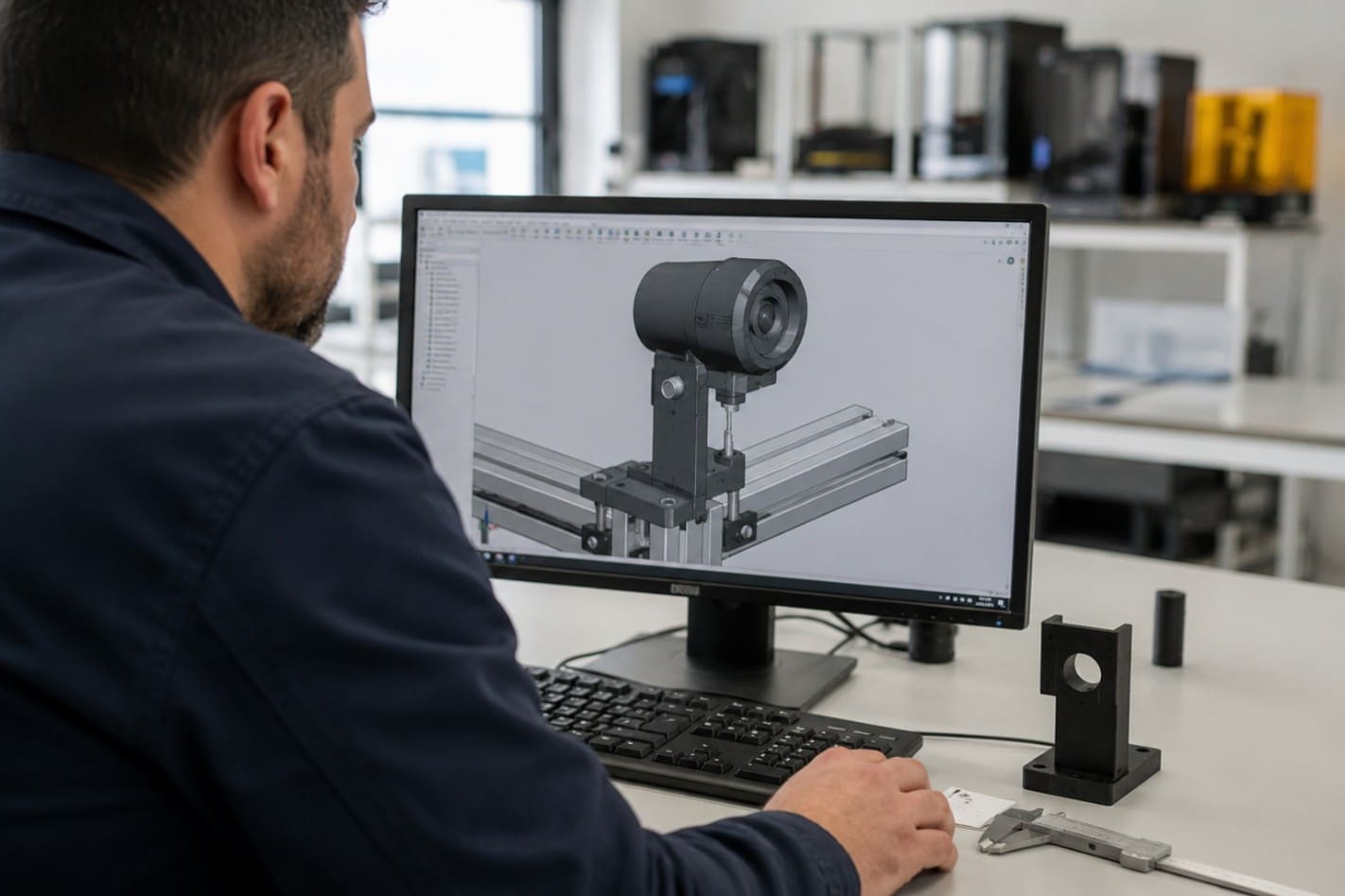
With the information gathered, the team tackled the 3D CAD modelling of all the mounts. Computer-aided design (CAD) makes it possible to build each part as a precise three-dimensional model and check on screen how it fits with the rest of the assembly before manufacturing anything.
Working with professional CAD software brings two concrete advantages in a project like this. The first is fit verification: the model is compared against the measurements taken on site, and interferences, clearances or lack of access are detected before printing. The second is adaptability, since modifying a dimension or an adjustment range in the model is immediate compared with the cost of remaking a physical part.
3D CAD modelling makes it possible to verify how each mount fits with the existing setup before manufacturing, and to absorb design changes at no material cost.
That adaptability was key to responding to possible variations in the process. The variable-position mounts were resolved in the model by defining the necessary degrees of freedom and their limits, so that the adjustment was intentional and repeatable, and not the result of a clearance. The guides, housings and adjustment elements that an adjustable mount requires are incorporated directly into the design, taking advantage of the geometric freedom that additive manufacturing later offers. A mount that moves when it should not is as problematic as one that cannot move.
The digital model also serves a documentary function: it fixes the validated geometry, serves as a basis for future modifications and allows the client to reproduce or adapt the parts later on. This capability is part of mechanical development, where CAD design connects the product with its real manufacturing.
3D printing, assembly and testing on the real setup
All the mounts were manufactured through 3D printing, an additive manufacturing technique that builds the part by depositing material layer by layer from the digital model. For single parts or very low quantities, such as a set of mounts for a specific setup, it is the direct answer to the assignment’s two constraints, limited time and contained cost: it requires no prior manufacturing tooling or minimum runs, and avoids the lead times and investment of a conventional machining or injection process, reserved for larger runs. The possibilities and limits of this technology are detailed in the industrial 3D printing service.
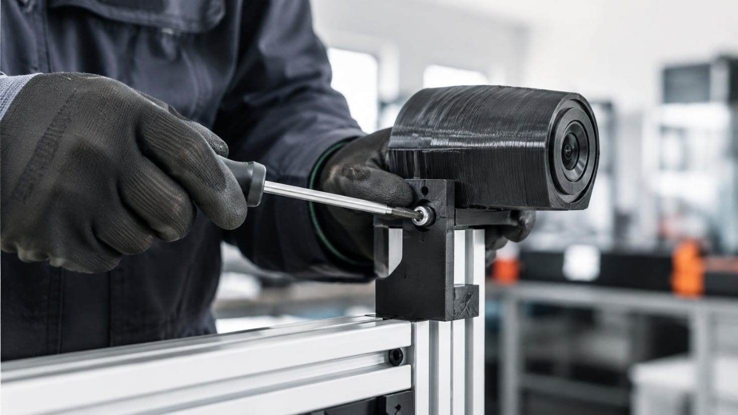
Once all the parts were obtained, assembly was carried out at the client’s premises. This step checks that each mount fits in the setup, that the camera stays firm in its position and that the adjustment elements work as planned. Since each mount is manufactured exactly as designed, a modification means reprinting the part rather than remaking a tool.
Testing under real conditions is what separates a correct design from a validated solution. A mount may comply in the model and fail during assembly because of an interference with a cable, a vibration transmitted from the structure, or an access that is awkward for the operator. Only the test on the real assembly makes it possible to confirm the mechanical integration and the reliable operation of the setup.
Testing under real conditions confirms that the mounts integrate into the setup and that the camera keeps its position throughout the test.
The result of the project was clear: within a limited timeframe and thanks to rapid prototyping processes, the client obtained the mounts they needed, assembled and tested on their setup, and with them they were able to carry out the planned tests. The mechanical solution ended up complete, stable and validated in its context of use, which was exactly the initial need.