
What was the challenge or problem to solve?
3D rendering from 2D drawings makes it possible to obtain photorealistic images of a product when the company only has flat documentation and does not keep the three-dimensional models of its parts. This is a more common situation than it seems in industrial settings: the product definition lives in development drawings and dimensioned views, while visual communication requires volume, materials and finishes.
In this project, an industrial company needed to renew the images in its assembly and user manuals. It provided 2D documents illustrating the views it wanted to obtain, but the graphic material it had previously achieved had not proved competitive. For this reason it contacted INFINITIA and the Product Development team.
Assembly and user manual: the graphic material the client needed
An assembly and user manual is the document that explains how to assemble, install and use a product. Its effectiveness depends directly on the illustrations: when an image does not make clear how a part fits, the user interprets, and that interpretation lies behind much of the incorrect assembly and the queries to technical support. In a manual, the image does not accompany the text, it replaces it.
The client’s need was specific: to have views of the product and its assemblies with enough quality to illustrate that documentation. It was not looking for a redesign or a functional validation, but for graphic material that faithfully represented what it already manufactured, with a level of finish comparable to its existing manuals.
The trigger was dissatisfaction with the previous results. The images obtained earlier had not proved competitive, a frequent diagnosis when the representation does not convey the real volume of the parts, the materials look flat, or the lighting erases the details the user needs to distinguish in order to assemble the product.
That starting point defines the purpose of the project and explains why it was approached from product development and not from a purely graphic angle. The goal was not to generate attractive images, but photorealistic product images that fulfilled an informative function within the documentation. There are normative references dedicated specifically to preparing product usage information, such as IEC/IEEE 82079-1, which place the comprehensibility of the information at the centre of a manual’s quality.
2D drawings as the only starting documentation, without 3D models
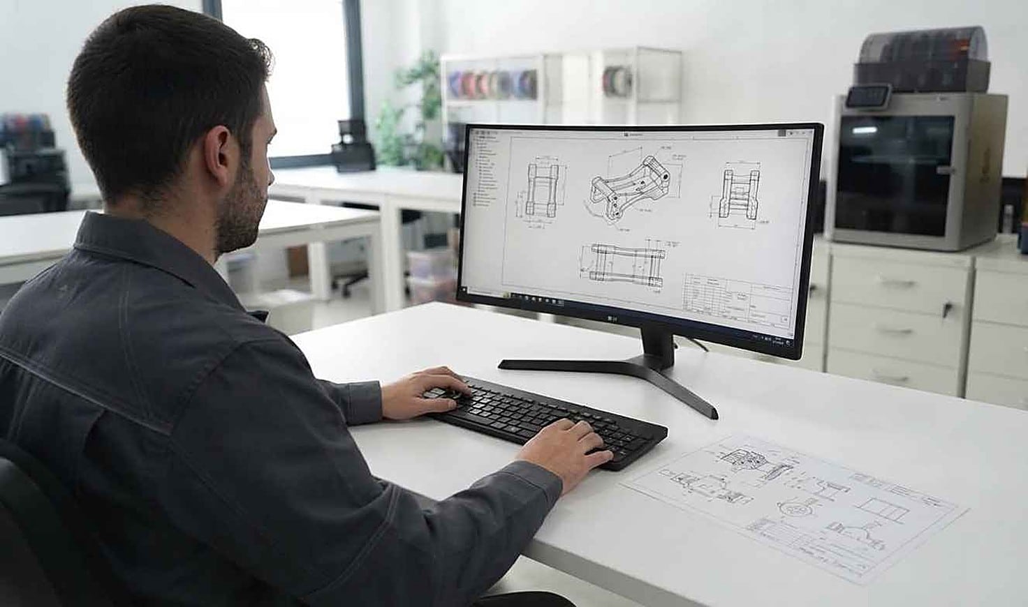
The underlying limitation of the project was clear: the client did not have the 3D material of its parts. The existing documentation consisted of 2D development drawings, that is, flat, dimensioned representations that define the geometry through views, sections and details, following technical drawing conventions such as those in the ISO 128 series of standards.
A 2D drawing contains the information needed to manufacture a part, but it is not a three-dimensional object. It cannot be freely oriented in space, it cannot be assembled with other parts and it cannot be lit. Any rendering engine, the program that computes the image by simulating how light behaves on surfaces, needs three-dimensional geometry, and that geometry did not yet exist.
There was also a relevant nuance: the 2D documents provided by the client also indicated the views it wanted to obtain. They marked the expected result, but did not provide the means to reach it. The project had to first reconstruct what was going to be represented and, only then, orient it in the requested position and framing.
Without a 3D model there is no render: a 2D drawing defines the part for manufacturing, but does not provide the geometry in space that any rendering engine needs.

Reconstructing the geometry from drawings requires technical interpretation, not simple transcription. You have to understand what each view represents, how they relate to each other and which constructive details condition how the parts fit together. It is work close to what the team specialising in mechanical product development does when starting from incomplete or scattered documentation.
Photorealistic rendering of assemblies with different materials
The technical challenge INFINITIA took on was to obtain realistic images of assemblies made up of parts of different materials. A photorealistic render is a computer-generated image that reproduces how light behaves on surfaces with enough fidelity to be perceived as a photograph.
The difficulty grows with the variety of materials. Each surface responds to light in its own way: polished metal reflects the environment directionally, a technical plastic diffuses the light, a textured finish breaks up the reflections, a translucent element lets part of the radiation through. An assembly that brings several of these behaviours together in a single image multiplies the necessary adjustments and the chances that the result looks artificial.
On top of that requirement came another equally demanding one from the client’s point of view: the new images had to keep the style it already used in others of its manuals. The result could not be only realistic, it had to be recognisable and consistent with the published documentation, so that the material as a whole did not lose its unity.
That dual condition, realism and visual continuity, is what turns an apparently graphic assignment into product engineering work. It requires reconstructing precisely, representing with physical criteria and, at the same time, subjecting the result to a pre-existing visual language that cannot be altered.
How was it addressed or what was the solution?
The solution was structured in two chained phases: first the generation of the non-existent 3D material and then the application of materials and the final rendering of each view. The order is not arbitrary, each phase resolves a specific gap and enables the next.
The work was carried out by INFINITIA’s Product Development team within its product design and innovation service, supported by professional modelling and rendering software. The tool, however, was not the differentiating factor: powerful software does not make up for badly reconstructed geometry or a wrong material criterion, and what determines the result is the technical decision behind each adjustment. The goal stayed dual throughout the project: geometric fidelity to the drawings and visual fidelity to the client’s style.
3D modelling from 2D drawings: parts and assemblies
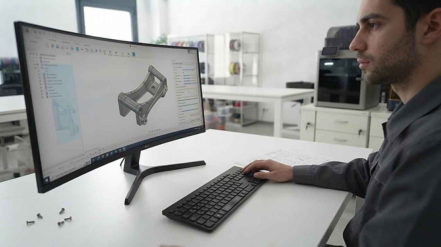
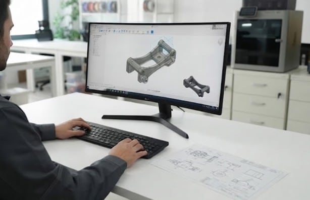
The first task was to generate, using professional software, the 3D models of all the parts from the documentation provided. 3D modelling is the process of building the three-dimensional representation of an object by defining its geometry, its surfaces and its dimensional relationships.
Modelling individual parts was not enough. It was necessary to obtain the assemblies, that is, to position each component in its place within the whole, with its real contacts and orientations. Only a correctly assembled whole makes it possible to then orient it freely and extract exactly the views the client had defined in its 2D documents.
The 3D modelling of all the parts was the step that made the rest of the project possible: without an assembled model, the requested views cannot be oriented or extracted.
This step is equivalent, in practice, to giving the product back its third dimension. The company thus recovered a digital asset it did not have and whose value exceeds the one-off assignment, since a three-dimensional model equally serves for new views, for future versions of the manual or for other technical uses within product development.
Precision in this phase conditions everything else. A geometric error is not corrected afterwards with lighting or materials: it carries through to the final image and appears right where the manual’s user is going to look, at the joint between two parts.
Material assignment to make the render look realistic
With the assemblies built, the corresponding material was applied to each part using rendering software. Material assignment consists of defining how each surface responds to light: colour, roughness, degree of reflection, transparency or texture, among other properties.
This is where realism is decided. Geometry provides the shape, but what the eye interprets as real is the coherence between surface and light. That is why the task was not limited to choosing a library material: it required adjusting the parameters of each one until the optical behaviour was believable part by part and within the whole.
The time invested in this phase is justified by its direct impact on the result. It is the material assignment that makes a render look realistic and, at the same time, the one that allows it to be adapted to the style of the manuals already published by the client. Two goals solved in the same adjustment.
It is worth stressing the difference from a conventional CAD view. A CAD view shows geometry; a photorealistic render shows a product. That distance is precisely what the client had not managed to cover with its previous results, and what explains the value of product rendering as a technical communication tool.
Final renders per view and consistency with the existing style
Once the material adjustment was complete, the final render of each of the requested views was obtained. Each image was generated from the 3D assembly oriented according to what the client had marked in its starting documents, so that the correspondence between what was requested and what was delivered was direct and verifiable. Computing all the views under the same criterion also prevents them from looking disparate when they coexist in a single document, a common problem when each image is generated independently.
The project is considered a success because realistic images were achieved that keep the style used in the rest of the company’s manuals. Visual continuity was an explicit requirement and it was met without giving up realism, which was the other requirement. The client went from not having 3D material to having photorealistic views that can be integrated into its documentation.
A render adds value when it integrates into the existing documentation: realism and visual consistency are simultaneous requirements, not alternatives.
This kind of work sits at the border between technical development and product communication, alongside resources such as final presentations and infographics, which explain how a product works or is structured by combining photorealistic images, exploded views and added information.
When a project starts from 2D drawings, from parts without a three-dimensional model or from graphic material that is not up to the product, the first step is always the same: review what documentation exists and what needs to be reconstructed.