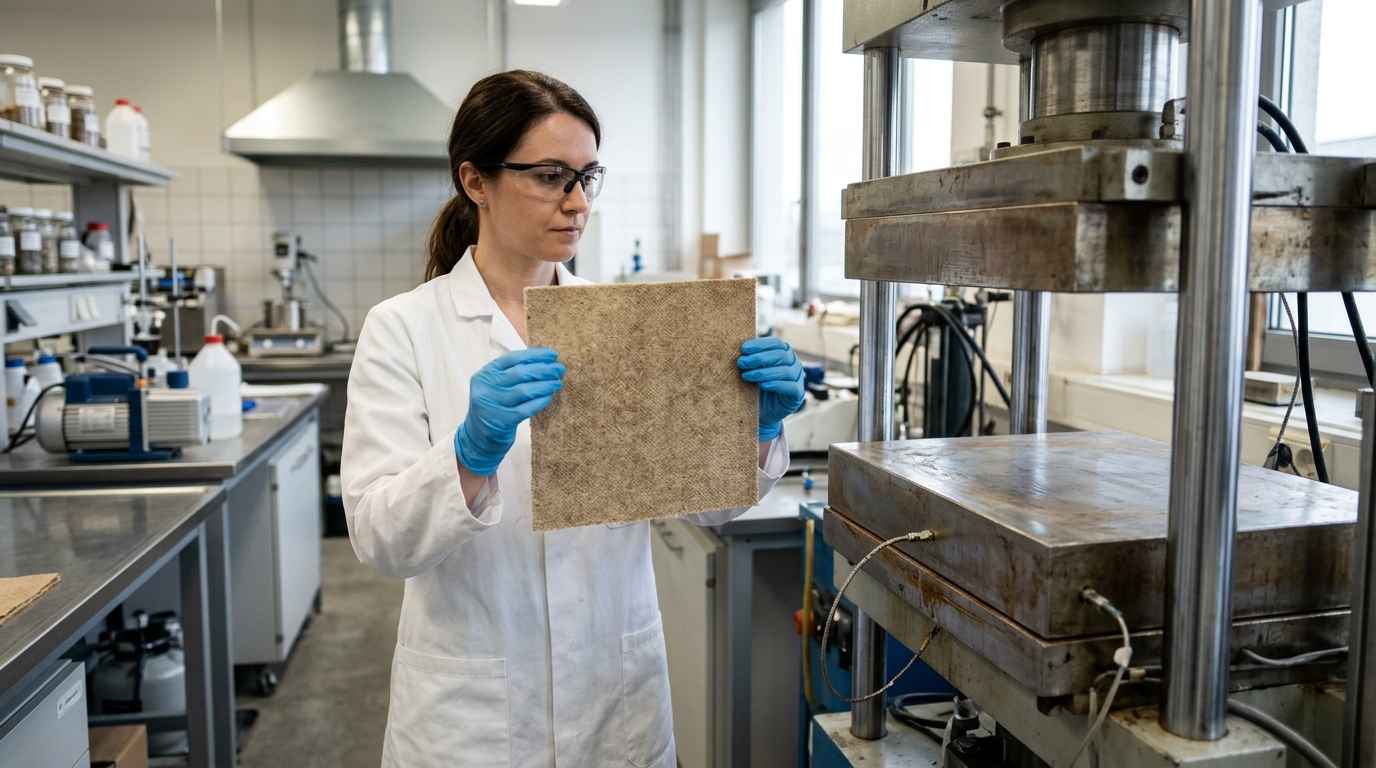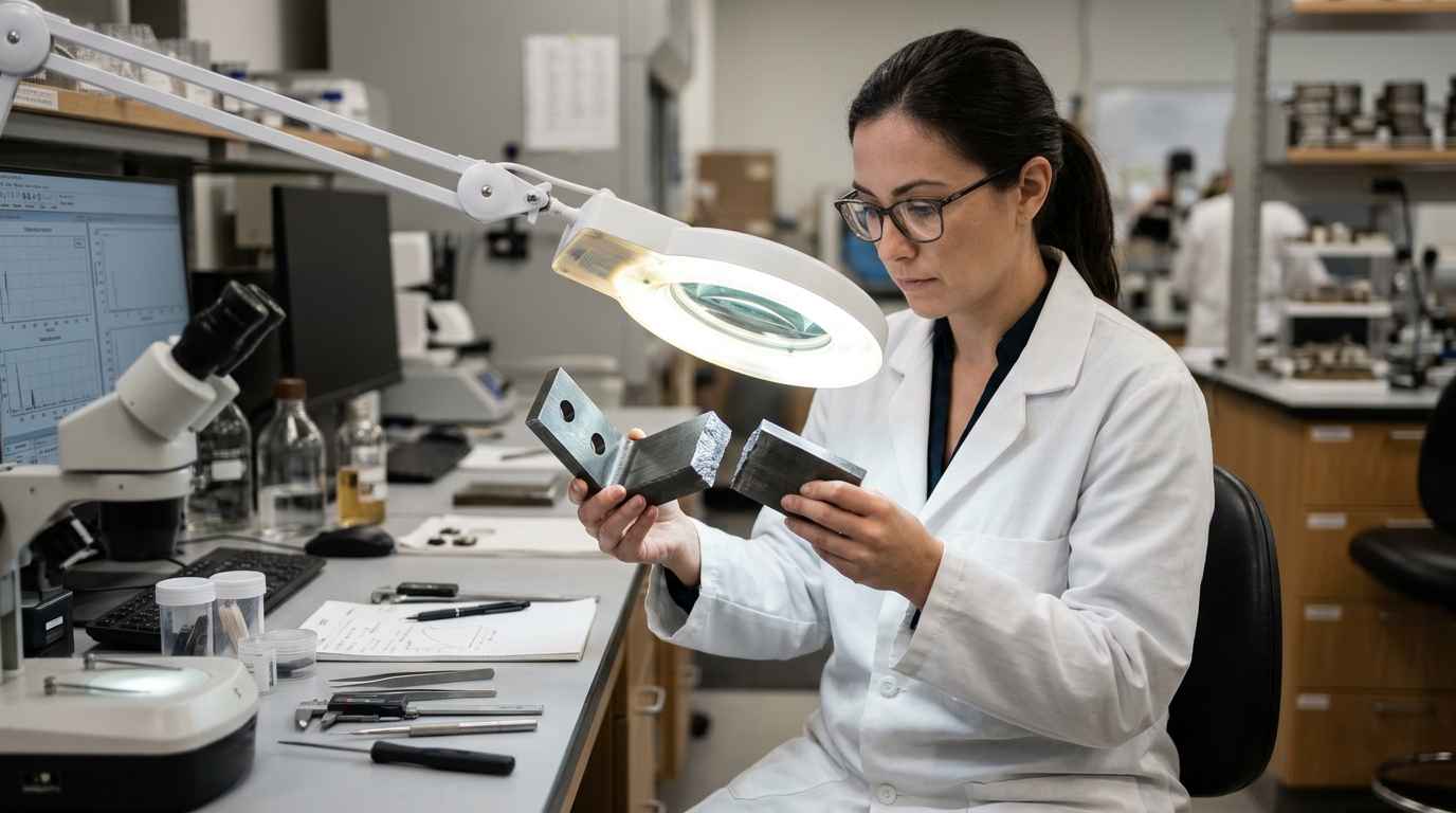

Destructive and non-destructive testing are the two routes for examining a failed part, the first cuts, polishes or breaks it to read its interior and the second inspects it without altering it.
In failure analysis the choice is not theoretical, because the broken part is often unique and every cut is irreversible. Within forensic engineering, non-destructive testing comes first because it allows you to document, locate internal defects and decide where to cut without sacrificing anything that still has to be seen.
That same logic of examining without destroying is the basis of reverse engineering, which reconstructs how a component is made before touching it. The destructive route comes later, on chosen areas, when the question requires seeing the microstructure, the fracture surface or the exact composition of the material.
REVERSE ENGINEERING
Need to see inside a failed part without cutting it or losing the evidence? Take a look at our reverse engineering

What destructive and non-destructive testing means in failure analysis
A non-destructive test is any technique that obtains information from the part without changing its condition, so that testing can continue afterwards. A destructive test is one that consumes the part or a portion of it, whether by cutting it, preparing it for the microscope or taking it to fracture. In failure analysis the two routes do not compete, they are chained together, and the quality of the conclusion depends heavily on the order in which they are applied.
Non-destructive testing, looking at the part without altering it
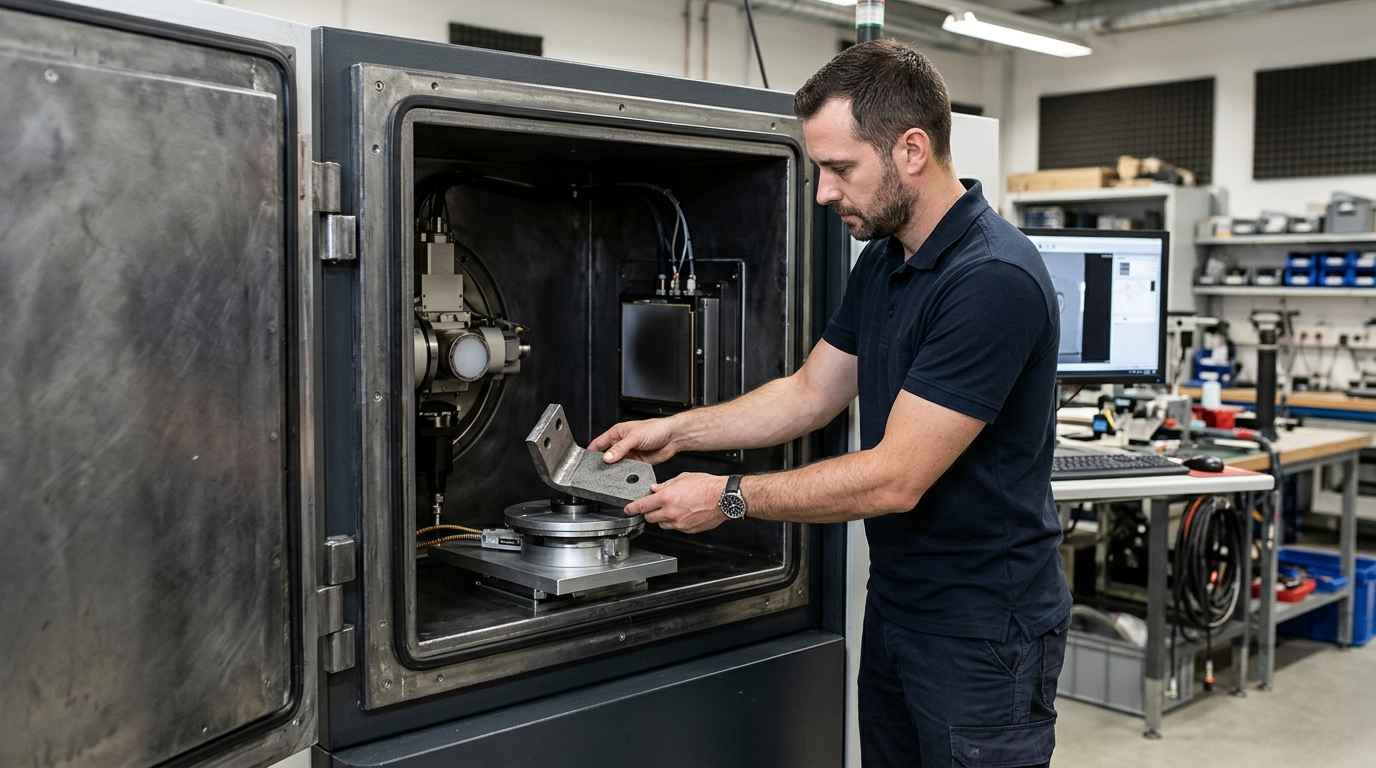
The non-destructive route starts with the simplest step, visual inspection under good light and the stereomicroscope, which show where the fracture started and whether there are beach marks, plastic deformation, corrosion or wear. It continues with techniques that see inside, such as radiography or computed tomography, able to locate pores, internal cracks, shrinkage cavities or badly assembled parts without opening the assembly.
For specific defects, ultrasonic testing, liquid penetrants or magnetic particles are used, and for a first idea of the composition, portable X-ray fluorescence. The qualification of the personnel who apply these techniques is governed by ISO 9712, and the overview of non-destructive tests and when to apply them helps to place each method by its scope. Its limit is clear, it describes geometry and surface, but it rarely explains why the material behaved the way it did.
Destructive testing, opening the part to read the mechanism
The destructive route answers the question of mechanism. A polished and etched cross-section reveals the microstructure, the grain size, the inclusions or a hardened layer that did not reach the intended depth. The preparation of these metallographic specimens follows guides such as ASTM E3, because poor polishing introduces artefacts that can be mistaken for real defects.
This family also includes fractography in the scanning electron microscope (SEM), which distinguishes a fatigue fracture from an overload fracture, hardness and tensile tests on specimens taken from the part, and laboratory chemical analysis, which compares the actual composition with the specified one. All of them give firmer answers than the non-destructive route, at the cost of using up material.
In plastics, elastomers and composite materials the boundary shifts. Infrared spectroscopy (FTIR) by attenuated total reflectance analyses the surface almost without damaging it and is enough to identify the polymer or a contaminant, while differential scanning calorimetry (DSC) consumes a few milligrams and tells you whether the material is degraded or poorly processed. In a composite, tomography locates the delaminations and the polished section confirms their origin.
Non-destructive tests tell you where and how much, destructive tests tell you why. A failure investigation needs both answers, but it can only obtain the first without sacrificing the part, which is why it always goes first.
Why the order of the tests decides what you can prove
The order of the tests decides what can be proved because each destructive step removes evidence that cannot be recovered. If you cut before documenting, the crack initiation area may end up on the wrong side of the cut, and if you clean before observing, the deposits or corrosion products that pointed to the cause disappear.
Preserving the evidence before the first cut
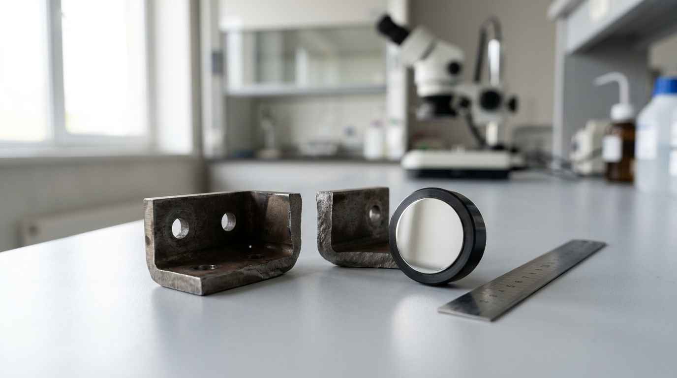
Preserving the evidence means photographing the part as it arrives, with a scale and from several angles, recording its origin and condition, and applying every useful non-destructive technique before touching it. Fracture surfaces are not fitted back together to see whether they match, because the rubbing flattens the fine details that fractography needs to read.
It is also worth recording who receives the part, how it is packed and where it is kept between tests. That chain of custody looks like paperwork until someone asks whether the part analysed is the same one that was removed from the equipment, and at that point it is the only thing that lets you answer with documents rather than memory.
This step opens any step-by-step industrial failure investigation, and it gains value when there is more than one part. Comparing the failed units with others from the same batch that have not failed, using the non-destructive route, lets you choose which one to sacrifice and which one to keep as a witness for later tests or for a second opinion.
When it pays to move early to the destructive route
There are failures in which the non-destructive route adds little and should not be prolonged. A brittle fracture with no visible defects, a part that does not reach the hardness on the drawing or a suspicion of the wrong material are resolved sooner with a metallographic specimen, a hardness measurement or a chemical analysis than with more external inspection. A useful criterion is to ask what the next non-destructive inspection would change, because if no pending technique can rule out a hypothesis, measuring from the outside only delays the cut and uses up time.
The decision depends on the question and on how many parts there are. With a batch of identical units, sacrificing one early is cheap and speeds up the answer. With a single part, coming from an in-service incident or a claim, every destructive test is planned carefully and justified before it is carried out, because there will be no second chance.
TELL US ABOUT YOUR CASE
Do you have a broken part on your desk and no idea which tests to run before opening it? Send us photos of the part as it is and a description of the failure and we will propose the test sequence
What each technique contributes to a failure analysis
Each technique answers a different question, and the value of a failure analysis lies in combining them to close the cause without leaving gaps. The table summarises what each one contributes, which route it belongs to and what it cannot tell you on its own, which is precisely what forces them to be chained.
Non-destructive techniques and their real reach
Non-destructive techniques are quick to apply and do not compromise the rest of the study, but their information is indirect. Tomography shows an internal cavity precisely, although it does not say whether it was born in casting, in welding or through corrosion. Portable X-ray fluorescence gives a steer on the alloy, but it measures the surface, does not detect light elements such as carbon well and cannot tell one heat treatment from another.
Size and material also determine what each technique can see. In tomography, the larger the part, the coarser the resolution, so a pore of tenths of a millimetre is clearly visible in a small housing and may go unnoticed in a large casting. Liquid penetrants only detect cracks open to the surface, and ultrasonic testing needs coupling and a geometry that allows the echoes to be interpreted.
| Technique | Route | What it reveals | What it cannot tell you |
|---|---|---|---|
| Visual inspection and stereomicroscopy | Non-destructive | Initiation area, beach marks, deformation and corrosion | Microstructure or composition |
| Radiography and computed tomography | Non-destructive | Pores, internal cracks, shrinkage and assembly errors | The chemical or metallurgical origin of the defect |
| Ultrasonic testing and liquid penetrants | Non-destructive | Internal cracks or cracks open to the surface | The mechanism that made the crack grow |
| Portable X-ray fluorescence | Non-destructive | Approximate elemental composition of the surface | Carbon, light elements or heat treatment |
| SEM fractography | Usually destructive, the area has to be cut | Fatigue, overload, embrittlement or stress corrosion | Whether the material met its specification |
| Metallography, hardness, tensile and chemistry | Destructive | Microstructure, properties and composition against the drawing | The real loads the part endured |
Destructive techniques and what only they show
Destructive techniques are the only ones that allow the material to be compared with its specification. A metallographic section shows whether a weld has lack of fusion, whether a steel has the structure that corresponds to its treatment or whether a coating has the intended thickness. A tensile test on specimens taken from the part tells you whether the material reaches the properties the drawing required, something no external inspection can confirm.
Their cost lies in the material they consume and in the preparation. A well-made metallographic specimen requires cutting, mounting, grinding, polishing and etching, and if the area is badly chosen, the work answers nothing. That is why the destructive route performs best when the non-destructive one has already pointed to where to look.
Laboratory chemical analysis completes what portable fluorescence cannot reach. Spark optical emission spectrometry gives the composition of a metal alloy precisely, and combustion analysis measures carbon and sulphur, two elements that decide whether a steel is the one the drawing asks for. Both consume a small portion of material, which is best taken from an area away from the fracture.
A well-placed metallographic section is worth more than ten random cuts. The non-destructive route does not replace the destructive one, it tells it where to cut so that each specimen answers a specific question.
How the two routes are combined in a failure investigation
A failure investigation combines the two routes in a sequence that goes from what preserves the part to what consumes it, from the general to the particular and from open hypotheses to the confirmed cause. Each step narrows the possible explanations and decides which destructive test is worth doing.
Test sequence from receipt to report
The usual sequence starts with documented receipt and visual inspection, continues with the non-destructive techniques that the geometry and material allow, and uses those results to form hypotheses. Only then is it decided which areas are cut, which specimens are extracted and in what order, leaving for the end the tests that use the most material, such as tensile testing.
An example of that progression is the failure analysis of metal parts that broke during industrial assembly, which started with a comparative visual inspection of broken and sound parts and then moved on to cross-sections and metallographic characterisation to study the internal structure of the material.
When the hypothesis points to a service condition, such as vibration or a thermal cycle, the sequence can end with tests on new parts that reproduce the failure in the laboratory. Those tests are also destructive, but they sacrifice units from the same batch instead of the failed part, and they confirm that the proposed cause is enough to explain the fracture.
Failed part against a reference part
A conclusion about a broken part is more solid when it is contrasted with a reference part that has not failed. If both have the same microstructure and the same hardness, the problem points to use or assembly. If they differ, it points to the material or the process. That is why it is worth asking from the start for sound units from the same batch and, if possible, from another batch that has not caused problems. In the analysis of the cause of failure of a component that broke in quality control, fractography in the scanning electron microscope was what made it possible to read how the fracture had progressed.
Destructive testing when a claim is involved
When the part may end up in a claim or in legal proceedings, destructive tests are planned differently. The prudent approach is to tell the parties what is going to be cut and when, so that they can attend or appoint their own technician, and to keep all the remains identified. A cut made without notice can be used by the other side to question the result.
In that context, the technical deliverable is an expert report that documents each test, its order and its justification, and which serves as the basis for the expert who signs the expert opinion. The traceability of the sequence, with photographs before and after each destructive step, is what allows the report to withstand an adversarial review.
In a failure with an open claim, the order of the tests is as important as their results. What was not documented before cutting can no longer be proved, however good the test that came afterwards.
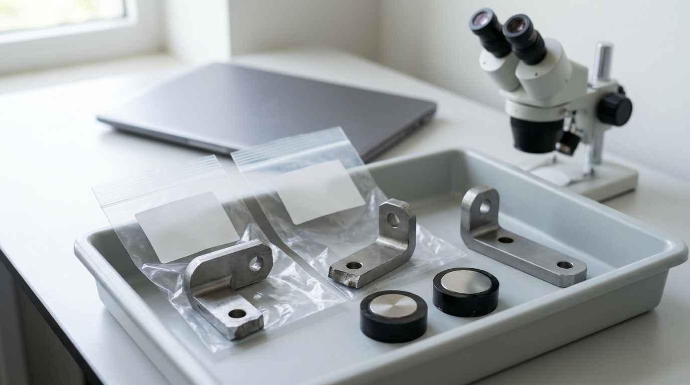
Choosing the route according to the question it has to answer
Non-destructive tests go first because they preserve the part, locate the defects and decide where to cut. Destructive tests come later because they are the only ones that explain the mechanism and compare the material with its specification. Neither route is enough on its own for most failures, and the one chosen at each step depends on the pending question, not on the technique that happens to be available.
What protects the result most happens at the beginning, not cleaning, not fitting the fractures together, photographing before touching and keeping reference parts. With that, every specimen that is sacrificed answers something specific and the final report rests on a sequence that anyone can reconstruct.
If you have a failed part that you have not opened yet, leave it as it is. Send photos of how it arrived, the context of the failure (when, under what service conditions and how many units) and, if you have them, sound parts from the same batch. With that information the non-destructive tests to do first, what is kept and what is sacrificed are defined, and you receive an analysis plan with the question each test answers.
Frequently asked questions about destructive and non-destructive testing
Can a failure analysis be solved with non-destructive tests alone?
Only in some cases, when the cause is visible from outside or from inside without opening the part, such as obvious overload deformation or a badly assembled component that shows up in a tomography scan. When the failure depends on the microstructure, the heat treatment or the exact composition, at least one destructive test on a chosen area is needed to confirm the cause.
In what order are destructive and non-destructive testing applied?
Non-destructive tests and documentation first, then destructive tests on the areas those results point to, and finally the ones that consume the most material. Visual inspection and tomography decide where to cut, metallography and fractography explain the mechanism, and tensile testing or chemical analysis confirm the material. The overview of destructive testing and when to apply it details what each one measures.
What factors determine the cost of a failure analysis using both routes?
The cost is determined by the number of parts, the techniques the case requires and the level of documentation in the report. A tomography scan or an SEM fractography costs more than a visual inspection, each metallographic specimen adds hours of preparation and an expert report requires more traceability than an internal one. To narrow it down, send photos and context before shipping the part to the failure analysis service.
What risk do you take if you cut a failed part before documenting it?
You risk losing evidence that cannot be recovered. The cut may pass through the crack initiation area, cleaning may remove deposits or corrosion products and handling may flatten the details of the fracture surface. If there is also a claim, the other side may question any conclusion that relies on a test carried out without prior documentation.
How long does a failure analysis combining destructive and non-destructive testing take?
Typical lead times range from one to four weeks, depending on the number of parts, the techniques required and the scope of the report. Depending on the case, there is an urgent 24 to 72 hour option for a first non-destructive assessment that helps decide whether to stop a line or hold a batch, while the destructive tests are completed.