
Leak testing checks whether a part, a package or a system stops liquids, gases or particles from passing between its inside and the outside within an acceptable leak rate, a property known as leak tightness. For electrical and electronic products it is complemented by IP and tightness tests, one of the areas of forensic engineering applied to quality control.
No part is perfectly tight: every seal lets something through. What gets specified is how much it can leak before the product stops working, loses its contents or becomes contaminated, and that is expressed as a maximum leak rate.
Automotive, medical devices, packaging, electronics, hydraulics and HVAC all design leak-tight products and need to verify them during development, on the production line and whenever a complaint comes in.
IP AND TIGHTNESS TESTS
Do you need to verify that your product is tight against water, dust or gas leaks? Discover our IP and tightness tests

What leak tightness is and how it is measured
Leak tightness is not a property of the material but of the assembly: it depends on the parts, the seals, the assembly and the pressure and temperature conditions under which it works.
That is why a leak test does not just check whether there is a leak, but whether the leak stays below the limit set by the specification. That limit should appear in the product or customer specification, together with the fluid and pressure it refers to.
Leak rate and acceptance criteria
A leak is quantified as a leak rate, that is, the amount of gas passing through the defect per unit of time, usually expressed in mbar·l/s or in cm³/min for a given pressure difference. Leak rates are often converted to an equivalent value for the real fluid and pressure, because the test is usually done with air or a tracer gas rather than the fluid the part will hold.
The acceptance criterion depends on the function. A water tank tolerates leaks that would be unacceptable in a refrigerant circuit, a sterile package or a potted sensor. Defining it properly is the first step, because it determines which test method has to be used.
A criterion that is too strict makes inspection expensive and causes needless rejections; one that is too loose lets through parts that will fail in service. EN 1779 sets out criteria for choosing the leak testing method and technique according to the sensitivity required.
Tightness against liquids, gases and particles
Being watertight is not the same as being gas-tight. Gas molecules pass through defects that water cannot get through, which is why a component that does not drip can still lose air or refrigerant pressure. Seals that are watertight at room temperature may also leak in the cold, when elastomers stiffen and lose contact pressure.
For electrical and electronic products, protection against solids and water is classified with the IP code of IEC 60529, whose ratings are explained in our article on IP protection. It is a test of behaviour against dust, jets or immersion, different from measuring the leak rate of a pressurised circuit.
A product is not simply tight or leaky: it is tight up to a specific leak rate, with a specific fluid and at a specific pressure. Without those three figures, a test result cannot be interpreted.
What a leak test is and how it is carried out
A leak test, also called a tightness test, checks whether an object or system meets the specified leak limit and, where needed, locates the leak. The same tests are used both for production checks and for validation during development.
It relies on a simple principle: fluid flows from the higher-pressure side to the lower-pressure side, so a controlled pressure difference is created and whatever passes through the defect is measured or observed. It belongs to non-destructive testing, because the part is left intact.
Before the test, the function of the part and its material
Before testing, you need to consider what the part was made for. Some automotive parts are designed to hold gases and an intravenous line to hold liquids; the test fluid, the pressure and the direction of the leak should reproduce that function.
The material matters too. A part that is too flexible deforms under pressure, changes volume and distorts the reading; a brittle part can be damaged if the test pressure exceeds the service pressure. That is why pressure, stabilisation time and temperature are fixed in the procedure.
It is also worth defining whether every part or a sample is tested, at which point in the process, and with which calibrated reference leak the equipment is checked, because without that reference you cannot know whether the system detects the limit leak.
Pressure decay and mass flow testing
In a pressure decay test, the part is filled with air to a set pressure, isolated from the supply and the pressure drop is recorded over time; that drop shows whether there is a leak and gives an estimate of its rate.
In a mass flow test, the part stays connected to the air supply to hold the target pressure, and a flow meter measures how much air has to be added to make up for what escapes. Both are fast and easy to automate, which is why they are common on production lines.
Their sensitivity depends on the part volume, the temperature and the test time, and they fall short for very small leaks, where tracer gases are used instead.
Vacuum decay and the differential method
Vacuum decay works the same way but with negative pressure: the part is evacuated and the pressure rise is monitored. It is useful when the part will work under vacuum or when it should not be pressurised.
The differential method compares the part with a tight reference volume at the same pressure; if the part leaks, a difference appears between the two. Because it compensates for part of the temperature effects, it detects smaller leaks than simple pressure decay.
In every pressure-based method, temperature is the most misleading variable: air that warms up or cools down inside the part changes pressure even without a leak, which is why freshly washed or welded parts must be allowed to stabilise before measurement.
TELL US ABOUT YOUR CASE
Are your parts failing the leak test and you do not know why? Send us the assembly and the test procedure and we will help you find where the leak comes from
Leak testing methods to locate the leak
Knowing that a part leaks is not enough to fix it: you have to find the exact point. Leak location methods complement global measurement methods and are chosen according to the expected leak size and the type of part. In many plants, a quick global test on every part is followed by a more sensitive location test only on the parts that fail.
The table summarises the most common methods, their principle and their typical use.
| Method | Principle | Typical use |
|---|---|---|
| Pressure decay | Measures the pressure drop in the pressurised, isolated part | In-line testing of medium leaks |
| Mass flow | Measures the flow needed to hold the pressure | In-line testing, large-volume parts |
| Vacuum decay | Measures the pressure rise in the evacuated part | Parts that work under vacuum |
| Bubble test | The part is pressurised underwater or coated with soap solution and bubbles are observed | Simple leak location |
| Tracer gas (helium or hydrogen) | A detector identifies the gas escaping through the defect | Very small leaks and precise location |
| Dyes and liquid penetrants | The liquid reveals the leak path | Surface cracks and pores |
| Burst test | Pressure is raised until the part fails | Safety margin of the design |
Bubble testing and dyes
The bubble test is the most intuitive: the part is pressurised and immersed in water, or a soap solution is applied to the joints, and the bubbles mark the leak. It is cheap and locates well, but it depends on the operator and does not quantify the leak rate accurately.
Dyes and liquid penetrants follow the same logic at the surface: the liquid enters cracks or pores and makes them visible. They help find the defect in welds, castings or moulded parts, not measure the leak.
Sensitivity improves with higher pressure, longer observation times and good lighting, but it remains a qualitative method, usually used to locate the leak after a part has been rejected in a quantitative test.
Tracer gas, helium and hydrogen
For very small leaks a tracer gas is used, usually helium or a hydrogen and nitrogen mixture. The part is filled with the gas and a detector, such as a helium mass spectrometer, picks it up outside; it can also be done the other way round, surrounding the part with gas and measuring what gets in.
In chamber mode, the part is placed in a sealed enclosure and all the escaping gas is measured, which gives a very sensitive overall leak rate. With a hand-held sniffer probe, by contrast, the part is scanned to pinpoint the exact location.
Helium is used because its molecules are very small, it is inert and its concentration in air is very low, which makes it easy to tell the leak from the background. Hydrogen diluted in nitrogen is a cheaper alternative for many industrial applications.
Burst, occlusion and other methods
A burst test raises the pressure until the part opens or breaks. It does not measure tightness in service but the safety margin of the design against overpressure. Occlusion testing detects blockages along the flow path, which is useful for tubes and ducts.
There are also specific methods, such as thermography, radioisotope detection or continuous pressure and flow monitoring in installations. The choice depends on the sensitivity required, the cost per part and whether the leak has to be located or only detected.
Detecting a leak and locating it are two different problems. A pressure decay test tells you the part fails; finding where and why usually takes another method and, often, an analysis of the design or the assembly.
Seals, sealing and the causes of leak test failures
Most leaks occur at joints: seals, threads, welds, bonded areas or contact zones between parts. That is why the sealing design matters as much as the material of the part.
When a test fails, failure analysis looks for whether the root cause lies in the design, manufacturing, assembly or ageing of the materials.
Types of seals and sealants
Seals close the contact between two surfaces, static or moving. Industry uses O-rings, flat gaskets, hydraulic and pneumatic seals, piston seals, rotary shaft seals, spring-energised seals, metal seals and EMI/RFI gaskets, which also block electromagnetic interference.
Sealants fill the gap between surfaces and stop fluids, dust, noise or heat from passing. They can be rigid or flexible, temporary or permanent, and must be compatible with the materials they join and the fluid they retain. Groove dimensions, compression ratio and the finish of the seating faces are as important as the seal compound itself.
Elastomeric seals gradually lose their ability to recover through compression set, hardening or chemical attack. Accelerated ageing tests make it possible to anticipate when they will stop sealing.
Design and assembly faults
Interference between parts, misalignment, insufficient or excessive tightening, wrongly sized seals or seating surfaces with unsuitable roughness are frequent causes of leaks that have nothing to do with the material.
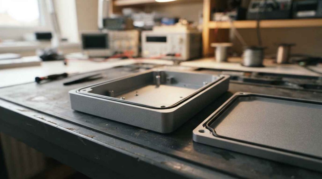
In the case of 3D printing to detect design flaws in leak-tight parts, parts that leaked during testing were analysed in CAD, revealing interference and misalignment issues. After the redesign, prototypes were 3D printed in transparent resin to make assembly and testing of the new design easier.
Stacked tolerances, shrinkage of moulded parts or deformation under tightening can open gaps that do not appear on the nominal drawing, which is why tolerance analysis is part of designing a leak-tight assembly.
Custom tests for large equipment or real conditions
When the part is very large or its service conditions are not covered by a standard test, the set-up has to be designed. Custom set-up tests reproduce the real pressure, temperature, cycles or exposure of the product. Before building the set-up, the applicable standard and the acceptance criterion have to be turned into a test sequence that can be repeated and audited.
That was the situation in an IP5X test on large equipment: standard dust chambers could not accommodate its size, so IEC 60529 was analysed, a specific set-up was designed and built, and it was validated with an accredited certification body before the test was run.
When a part leaks, changing the seal is the quickest fix and the least reliable one. If the cause is interference, tightening or a poorly finished surface, the new seal will fail just the same.
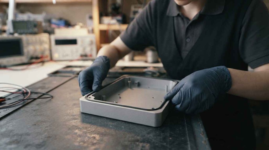
Leak tightness is specified, measured and validated
Leak tightness is the ability of an assembly to keep its leak rate below a limit, with a specific fluid and pressure. Pressure decay and mass flow tests verify it in-line; bubble, dye and tracer gas methods locate the leak; and IP tests classify protection against dust and water. Choosing the right method starts with a clear acceptance criterion.
If you need to validate the tightness of a product, or your parts are failing the leak test, send us the part or assembly, the drawing, the working fluid and pressure and the acceptance criterion. We will propose the right test method and, if there is a failure, the analysis needed to find its cause.
Frequently asked questions about leak testing
What is leak tightness?
Leak tightness is the ability of a part, package or system to stop liquids, gases or particles from passing between its inside and the outside. Since no seal is perfect, it is defined as keeping the leak rate below a limit for a given fluid and pressure. It applies both to products, such as a sensor or a container, and to installations, such as a hydraulic circuit or a pipeline. Leak testing is the set of methods used to verify it, in fuel systems, refrigeration circuits, medical devices or sealed electronics, for example.
What is the difference between a leak test and an IP test?
A leak test measures whether a pressurised or evacuated object loses fluid and how much, usually as a leak rate. An IP test, under IEC 60529, classifies the protection an enclosure offers against the ingress of solids and water by exposing it to dust, dripping, jets or immersion. They are complementary: an electronic device may need a specific IP rating and, at the same time, an internal circuit with a maximum leak rate.
Which leak testing method should you choose?
It depends on the sensitivity required, the volume of the part, the acceptable cost per test and whether the leak has to be located or only detected. Pressure decay and mass flow are fast and can be automated for in-line testing; bubble testing locates leaks simply; and tracer gas with helium or hydrogen detects very small leaks. EN 1779 provides guidance on choosing the method according to the leak rate to be guaranteed. For small batches, a bubble test after a pressure decay rejection is often enough to find the defect.
Why does a part fail the leak test even with a new seal?
Because many leaks are not caused by the seal but by interference between parts, misalignment, incorrect tightening, poorly finished seating surfaces or seals that are wrongly sized for their groove. The test itself also plays a part: insufficient stabilisation or a temperature change during the test alters the pressure and can cause false rejections. Reviewing the design, the assembly and the procedure usually solves the problem before you change seal supplier.
When should you outsource leak testing?
It makes sense when you lack equipment with the required sensitivity, when the part is so large or unusual that it needs a custom set-up, when you need to prepare a product for an IP test or when parts fail and the cause has to be found. It also makes sense when you want to define the acceptance criterion and the method before installing in-line testing. If any of these applies, tell us about your case and we will propose how to tackle it. A first review of your existing test procedure often shows whether the problem lies in the part or in the measurement.