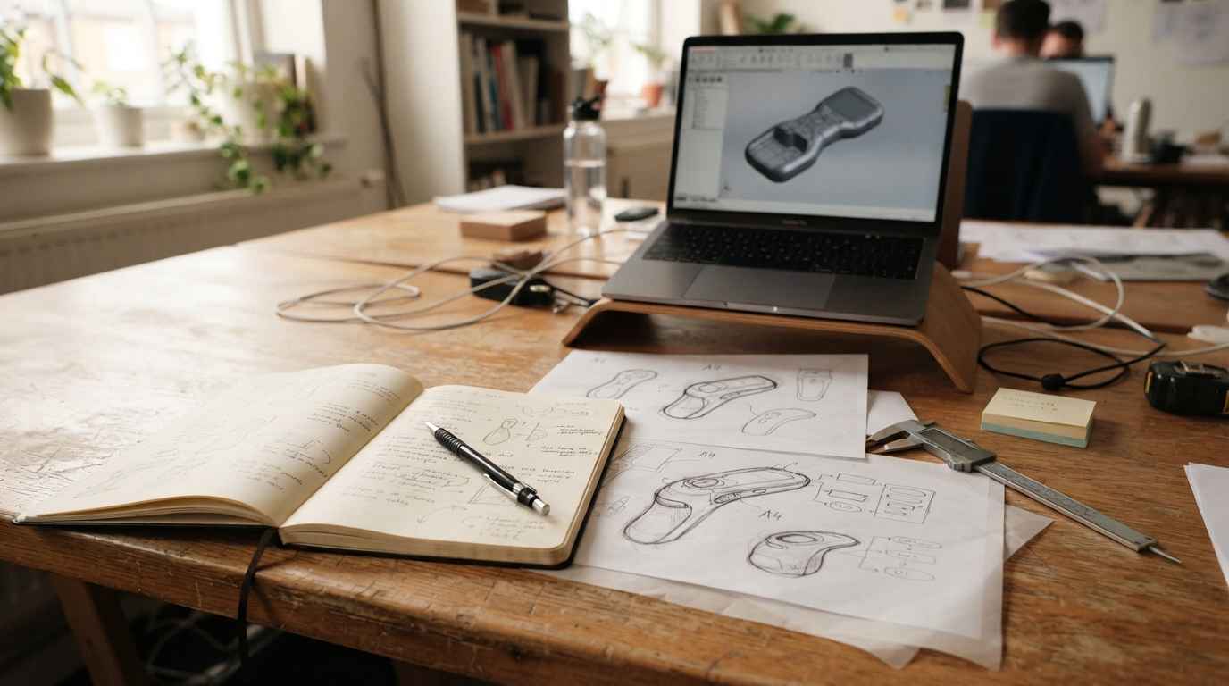

Reverse engineering an obsolete component is the disciplined process of recovering the geometry, material and function of a part that is no longer manufactured, so it can be reproduced reliably and safely. When a supplier disappears, a production line stops or a critical spare part vanishes from the catalogue, the original drawings are frequently missing, incomplete or protected. The physical part becomes the only surviving source of truth, and extracting all the engineering information it contains is the difference between a component that works and one that fails in service. It is part of the wider product development process.
The temptation is to measure a few dimensions, model the shape and send it to a machine shop. That approach copies appearance while discarding the properties that make the part fit, seal, transmit load or resist fatigue. To reverse engineer a discontinued part correctly means treating the object as a system: capturing its form, identifying what it is made of, understanding what it does, and validating the reproduction before committing to a series.
REVERSE ENGINEERING
Do you need to reproduce an obsolete component with no drawings? Discover our reverse engineering service

Why a component becomes obsolete and why that is a problem
Obsolescence is rarely a single event. A part is discontinued when the business case for producing it disappears: the original equipment manufacturer redesigns a product, a foundry closes, a specialised alloy is deregistered, or demand falls below the volume that justifies tooling. The component itself may still be perfectly fit for purpose, yet no legitimate source remains. This is the core of the obsolescence problem in industry, and it affects sectors where equipment lifecycles are measured in decades, such as rail, energy generation, industrial machinery and capital goods.
Obsolescence is an economic decision made upstream, but its consequences land downstream as unplanned downtime, safety exposure and the loss of the only documented design intent for a component still in active service.
When a vanished supplier takes the manufacturing knowledge of a component with them, the loss extends far beyond a purchase order. Legacy machinery, some of it installed thirty or forty years ago, often depends on parts that were never widely standardised: a specific bearing housing, a cam profile, a bespoke gear, a hydraulic manifold. If one of these fails and no replacement exists, the entire asset can be immobilised. The financial exposure is disproportionate to the size of the part, because the cost is dominated by lost production rather than by the piece itself.
Reproducing an obsolete spare part restores control over the asset’s lifecycle. Instead of scrapping a functioning machine because a single component cannot be sourced, an operator can recover the design, verify it and manufacture on demand. This is a common driver in maintenance-heavy environments, where reliable reproduction of a legacy part extends the useful life of expensive equipment and defers major capital expenditure. Structured product development methods make that recovery repeatable rather than improvised.
When you cannot simply buy the part: the case for reproducing an obsolete spare part
Reproducing an obsolete spare part becomes the rational option when the alternatives are worse: redesigning the host system around a modern component, importing an unverified substitute, or accepting the asset’s retirement. Each of those carries its own engineering and commercial penalties. A redesign may cascade into requalification of the whole assembly. An unverified substitute may fit dimensionally yet behave differently under load or temperature.
The decision to reproduce is therefore a risk-management decision as much as a technical one. It is justified when the component is well defined, the failure mode is understood and the reproduction can be validated against the original function. The engineering task is to reconstruct enough of the original design intent that the new part is interchangeable with the old one, not merely similar to it. That distinction, interchangeable versus similar, runs through every step that follows.
The three layers of reverse engineering: geometry, material and function
A robust methodology treats every component as three superimposed layers of information. Geometry describes the shape and dimensions. Material describes what the part is made of and how it was processed. Function describes what the part must do in its assembly. Copying only the first layer produces a lookalike; recovering all three produces an engineering equivalent. This layered view is the conceptual backbone of any serious effort to reverse engineer a discontinued part, and it maps directly onto disciplined mechanical development.
The broad practice of reverse engineering covers the full route from a physical object to a manufacturable, validated design. Skipping a layer is the most frequent cause of a reproduced part that disappoints in service.
Digitisation and geometric capture: 3D scanning, CMM and industrial CT
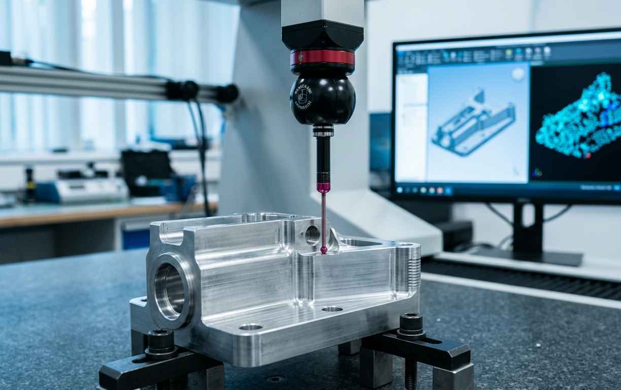
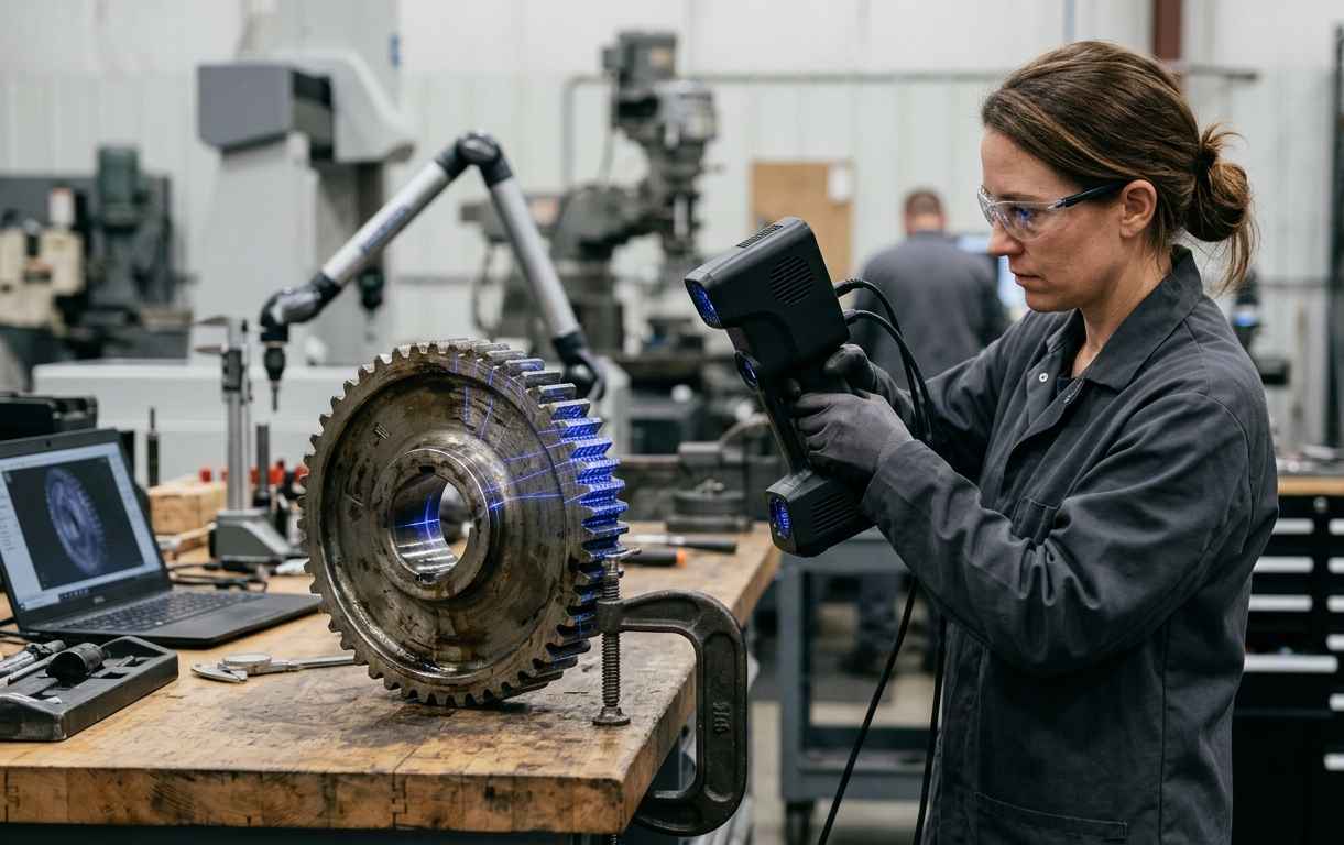
Geometric capture is the acquisition of the part’s exact shape as digital data, and the choice of technique depends on the geometry, the required accuracy and whether internal features must be measured. Structured-light and laser 3D scanning capture dense point clouds of external surfaces quickly, which is ideal for free-form shapes such as castings, housings and impellers. A coordinate measuring machine (CMM), a probe-based system that records precise point coordinates, delivers high accuracy on prismatic features, bores and datum surfaces where tolerance control is critical.
For internal geometries that cannot be reached by a probe or a line of sight, industrial computed tomography (CT) is decisive. Industrial CT is an X-ray technique that reconstructs a full three-dimensional volume of a part, revealing internal channels, wall thicknesses, cast porosity and hidden cavities without cutting the object open. This matters for hydraulic bodies, cooling passages and encapsulated assemblies, where the function lives inside the part and cannot be inferred from the outside.
A dense point cloud is not a drawing. Digitisation records where surfaces are; engineering judgement decides which of those surfaces are functional datums, which are nominal, and which carry the tolerances that govern how the reproduced component behaves.
Combining techniques is often the correct answer. A typical workflow scans external form, uses the CMM to lock down critical dimensions and datums, and applies CT where internal features or wall integrity are in doubt. The result is a metrologically sound description of the geometry that later feeds the CAD reconstruction rather than a decorative surface mesh.
CAD reconstruction converts captured geometry into an editable, parametric model that expresses design intent rather than a frozen mesh. A parametric model is built from features, sketches, extrusions, revolves and patterns, whose dimensions are driven by parameters that can be adjusted and verified. This is fundamentally different from a scan-to-mesh copy: it allows fits to be corrected, worn surfaces to be restored to their original nominal, and manufacturing constraints to be applied. Rigorous 3D design and modelling using CAD turns measured points into a controllable engineering definition.
A model without tolerancing is incomplete. Geometric Dimensioning and Tolerancing (GD&T), formalised in ISO 1101, is the language that specifies how much each feature may deviate in form, orientation, location and runout, and which datums govern those relationships. Applying GD&T during reconstruction ensures the reproduced part is defined by function, not by whatever the scan happened to record. A bore may need a tight cylindricity and a controlled position relative to two datums; a mounting face may need a defined flatness; a shaft may need concentricity to transmit rotation without vibration. Recovering these relationships, often eroded by wear on the sample part, is where reverse engineering becomes engineering rather than duplication.
Material identification: composition, metallography, hardness and treatments
Once geometry is captured and modelled, the part is still only described on the outside. The second and third layers, material and function, determine whether the reproduction will survive its service life. This is the stage most often skipped when a part is copied cheaply, and it is precisely the stage that separates a durable spare from a premature failure. Thorough material characterisation is what stops a reproduction from being a shape with unknown properties.
Material identification establishes what the component is actually made of and how it was processed, so the reproduction matches its mechanical behaviour and not just its appearance. Chemical composition is determined by techniques such as X-ray fluorescence (XRF) for rapid elemental screening and optical emission spectrometry (OES) for accurate quantification of alloying elements, including the light elements critical to steels. Knowing whether a bracket is a plain carbon steel, a low-alloy grade or a specific stainless family changes everything downstream, from strength to corrosion resistance to weldability.
Composition alone is not enough, because two parts of identical chemistry can behave very differently depending on processing. Metallography, the microscopic examination of a polished and etched cross-section, reveals grain structure, phase distribution and evidence of heat treatment. Hardness testing and, where samples permit, mechanical testing quantify strength and ductility. Surface engineering must also be recovered: case hardening, nitriding, anodising, galvanic or organic coatings all change how the part performs and must be specified for the reproduction. Determining the exact alloy through reverse engineering and comparative analysis is often what unlocks both performance and cost.
Copying the shape while guessing the material produces a part that looks identical and behaves differently. Under fatigue, temperature or corrosion, that difference is where reproduced components fail first, often without warning and at the worst possible moment.
Consider a gear reproduced in a mild steel when the original was a case-hardened alloy steel. Dimensionally it may be perfect and it may even run for a while, yet the tooth surface will wear or pit far sooner than the original, because the missing heat treatment was doing invisible work. In the automotive and industrial machinery sectors, this class of error is a frequent root cause in failure analysis of substitute parts.

Part of that characterisation means identifying heat treatment through metallography, which reveals whether the original part was hardened, normalised or annealed.
TELL US ABOUT YOUR CASE
Do you have a part to replicate without documentation? Send us the component and we will propose a reverse engineering project
From functional validation to manufacturing
Geometry and material are necessary but not sufficient. Before a reproduced component can be trusted in service, its tolerances and fits have to be recovered correctly and its function validated, and only then does it move to manufacture. This final thematic section follows that path, from functional validation through the manufacturing route to the technical and legal risks, including intellectual property, that must be managed deliberately before a series is released.
Tolerances, fits and functional validation before series reproduction
Tolerances and fits define how mating components interact, and recovering them correctly is essential when the only reference is a worn sample. The ISO 286 system of limits and fits describes clearance, transition and interference relationships between shafts and holes using standardised tolerance grades. A press-fit bearing seat, a sliding bushing and a locating dowel each require a specific fit; reading the nominal from a used part means compensating for wear and inferring the original intent. Surface finish, specified as roughness parameters, is part of the same functional picture, because a sealing face or a bearing journal depends on texture as much as on dimension.
Functional validation is the step that confirms the reproduction actually works before committing to a series. Validation may combine dimensional inspection against the GD&T definition, fit checks in the real assembly, material verification and, where the duty is demanding, functional or bench testing under representative load, pressure or temperature. Producing a first article, verifying it in context and only then releasing the design for series manufacture converts a plausible copy into a qualified spare. The same validation discipline underpins projects such as the design and manufacturing of an advanced functional prototype, where the object had to perform, not merely resemble.
From model to part: manufacturing and design for manufacturing
Manufacturing and design for manufacturing (DFM) determine how the reconstructed model becomes a physical component at acceptable cost and quality. The route depends on geometry, material and volume. Machining from bar or billet suits precise metallic parts in low quantities. Casting suits complex shapes reproduced in numbers, though it reintroduces the need to control alloy and microstructure. Additive manufacturing, or 3D printing, is increasingly used to reproduce discontinued parts with complex internal geometry or where tooling would be uneconomic for a handful of pieces.
Design for manufacturing adapts the model to its chosen process so the part can be produced reliably: adding draft angles for casting, ensuring tool access for machining, or orienting an additively built part to control anisotropy and support removal. A part originally cast decades ago might now be machined or printed, which can change residual stresses and grain structure, so the material and validation work described earlier must account for the new process. DFM is therefore not a cosmetic step; it is where the reproduced component is made both manufacturable and faithful to the original function.
The risks of copying without characterising a component are premature failure, incompatibility and liability. Premature failure arises when unrecovered material properties or heat treatments leave the part weaker than the original. Incompatibility arises when tolerances and fits are read from a worn sample without correction, so the new part does not seat, seal or align. Liability arises when a reproduced component fails in a safety-relevant application and no engineering basis for the reproduction can be shown. In regulated sectors such as rail and energy, the absence of traceable characterisation is itself a serious problem.
Legitimate reverse engineering exists to keep equipment running and to restore interoperability, not to clone a competitor’s protected design. The line is drawn by intent, by the presence of protectable rights, and by whether the work recovers function or merely appropriates it.
Intellectual property sets the second boundary. Reverse engineering for interoperability and for the maintenance of legitimately owned equipment, particularly to produce spare parts for assets already in service, is a widely recognised and lawful engineering activity. Copying a design that is actively protected by patents, registered designs or other rights is a different matter and can constitute infringement. A responsible approach distinguishes clearly between recovering the engineering information needed to keep an asset alive and reproducing a protected product for commercial competition. When in doubt, the scope of the work and the status of any rights should be clarified before manufacturing begins.
The table below summarises three fidelity levels of reproduction. It clarifies why a simple dimensional copy carries the highest in-service risk, and why full reverse engineering with characterisation and validation is the appropriate route for critical components.
| Fidelity level | What it reproduces | Techniques | In-service risk |
|---|---|---|---|
| Simple dimensional copy | External shape and basic dimensions only | Manual measurement, single-pass 3D scan, direct scan-to-mesh | High: material, tolerances and treatments unknown; likely fit or durability problems |
| Advanced geometric reproduction | Full geometry with tolerances and datums, but assumed material | 3D scanning, CMM, parametric CAD reconstruction, GD&T per ISO 1101, ISO 286 fits | Moderate: dimensionally sound, yet mechanical behaviour still not guaranteed |
| Reverse engineering with characterisation and validation | Geometry, material and function as an integrated equivalent | Geometric capture plus XRF/OES, metallography, hardness, first-article and functional testing | Low: interchangeable and qualified for its service duty |
Reliability comes from recovering all three layers
Reproducing a discontinued part reliably is not a matter of copying a shape; it is a matter of recovering the full engineering definition that made the original work. Geometry tells you where the surfaces are, material tells you how the part behaves under load, temperature and corrosion, and function tells you what the reproduction must actually achieve inside its assembly. A method that captures all three, and validates the result before series production, turns an unavailable component into a qualified, interchangeable spare rather than a hopeful lookalike.
The individual techniques, structured-light and laser scanning, CMM metrology, industrial CT, parametric CAD reconstruction with GD&T per ISO 1101, ISO 286 fits, composition analysis by XRF and OES, metallography and hardness, and first-article and functional testing, are only as valuable as the discipline that connects them. The most costly mistakes in reverse engineering are almost never failures of a single instrument; they are omissions, a skipped material analysis, an uncorrected worn dimension, an untested first article, that surface later as downtime, warranty exposure or a safety incident. Doing the work in the right order, and stopping to validate at the right points, is what makes the outcome dependable.
If you have a critical part with no spare and no drawings, send it to us or send photos and the equipment reference: we’ll assess whether it can be reproduced, what level of fidelity it needs and what it costs to get there.
Frequently asked questions
Can you reverse engineer a discontinued part without any original drawings?
Yes, a discontinued part can be reverse engineered from the physical component alone, without any original drawings. The part itself becomes the reference: its geometry is captured by 3D scanning, CMM and, where needed, industrial CT, while its material is identified by composition analysis, metallography and hardness testing. From this data an engineering definition is reconstructed, including tolerances and fits, so the component can be reproduced even when every trace of the original documentation has been lost. This is the standard situation when the goal is to replicate a component without drawings.
Why is material identification as important as capturing the geometry?
Material identification is as important as geometry because two parts of identical shape can behave completely differently depending on their alloy and processing. A reproduction that matches every dimension but uses the wrong steel, or omits a heat treatment or coating, can wear, fatigue or corrode far sooner than the original. Recovering composition, microstructure, hardness and surface treatments ensures the reproduced part matches the mechanical behaviour of the original, not only its appearance. Detailed elemental analysis and chemical composition is central to getting this right.
Is 3D scanning enough to reproduce an obsolete spare part?
No, 3D scanning alone is not enough to reproduce an obsolete spare part reliably. Scanning captures external form and produces a point cloud, but it does not by itself define functional tolerances, datums, internal geometry or material properties. A dependable reproduction combines scanning with CMM metrology for critical dimensions, industrial CT for internal features, parametric CAD reconstruction with GD&T, material characterisation and functional validation. Scanning is an essential first step, not a complete solution.
Which manufacturing method is best for reproducing a legacy component?
The best manufacturing method depends on the part’s geometry, material and required quantity. Machining suits precise metallic parts in low volumes, casting suits complex shapes produced in numbers, and additive manufacturing, or 3D printing, is well suited to complex internal geometries or very small runs where tooling is uneconomic. The chosen process must be paired with design for manufacturing and with material validation, because changing the process can alter grain structure and residual stress compared with the original part.
Is it legal to reverse engineer a component to make spare parts?
Reverse engineering a component to produce spare parts for equipment you legitimately own is generally a lawful and recognised engineering activity, particularly when it restores interoperability and keeps assets in service. The legal boundary concerns intellectual property: reproducing a design that is actively protected by patents or registered designs for commercial competition can constitute infringement. The safe approach is to distinguish clearly between recovering the engineering information needed to maintain an asset and copying a protected product, and to clarify the status of any rights before manufacturing.