
Welding defects are discontinuities in a welded joint (porosity, lack of fusion or penetration, cracks, slag inclusions, undercut) that reduce its strength or tightness. You detect them by combining non-destructive testing on the part with destructive laboratory examination of representative samples, and you prevent them through a qualified procedure and process control.
Every weld you release into series production carries a history: how the joint was prepared, which parameters the welder used, how clean the base and filler metal were. When that history goes wrong, the result is a discontinuity that may pass unnoticed on the shop floor and surface later as a leak, a fatigue crack or a fractured assembly in the field. The discipline of analysis and improvement of welds exists to close that gap between what leaves the welding cell and what actually holds up in service.
Reading a joint correctly means pairing the right technique with the right standard, and knowing when a surface method is enough and when you need a cross-section under the microscope. An independent industrial engineering and materials testing laboratory gives you that reading without the bias of the party that produced the weld, which matters when a batch is disputed or a supplier change has to be validated.
ANALYSIS AND IMPROVEMENT OF WELDS
Do your welds show defects or fail in service? Discover our weld analysis and improvement service

What welding defects are and why they appear
A welding defect is any discontinuity or deviation from the specified geometry, soundness or metallurgical condition of a joint that falls outside the accepted quality level. The reference framework that names and groups them is ISO 6520-1, which classifies imperfections in fusion welding by type rather than by cause, so that inspectors across sectors describe the same finding with the same code.
Types of welding defects and their classification under ISO 6520-1
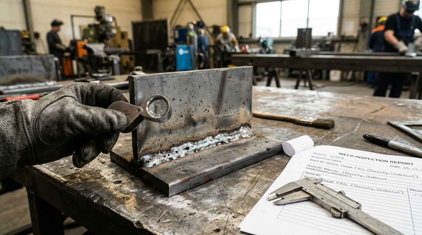
Porosity is gas trapped in the solidifying weld pool that leaves rounded cavities, either isolated or clustered, and it is the discontinuity most often linked to shielding or contamination problems. Lack of fusion is an absence of bonding between the weld metal and the base material or between passes, while lack of penetration means the weld root has not been filled to the required depth. Both leave the joint carrying less section than the drawing assumes.
Cracks are the most severe family. Hot cracks (solidification cracks) form while the weld is still freezing, usually along the centreline; cold cracks (hydrogen-induced or delayed cracks) appear hours after welding in hardenable steels when hydrogen, restraint and a hard microstructure coincide. Slag inclusions are non-metallic residues left between passes, and undercut is a groove melted into the base metal at the weld toe that acts as a stress raiser. Each of these has a distinct ISO 6520-1 reference, and naming the imperfection precisely is the first step toward tracing where in the process it came from.
Naming a discontinuity is not cosmetic. A cluster of rounded cavities and a linear absence of bonding may look similar on a rough radiograph, yet porosity and lack of fusion point to different process causes and carry very different consequences for fatigue life.
Where welding defects come from in the process
Most welding defects trace back to a small set of controllable variables: shielding gas and contamination, heat input, joint preparation and the metallurgy of the base and filler metal. Porosity commonly follows a loss of gas shielding, damp consumables or oil and rust on the joint. Lack of fusion follows insufficient heat input, too fast a travel speed or a poorly presented bevel that the arc cannot reach.
Cold cracking is a metallurgical outcome: dissolved hydrogen migrates to the hardened heat-affected zone of alloy or high-strength steel and, under residual restraint, initiates a crack after the joint has cooled. That is why preheat, hydrogen-controlled consumables and interpass temperature sit at the centre of any welding procedure for thick or hardenable sections. When you connect a defect back to its origin, you move from sorting bad parts to preventing them, which is where laboratory correlation earns its place alongside testing of metallic materials and alloys that characterises the parent material behind the joint.
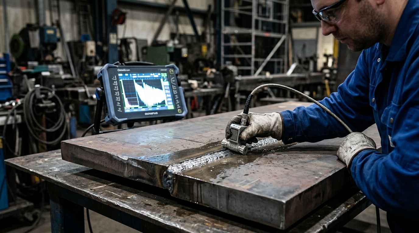
How welding defects are detected with non-destructive testing
Non-destructive testing (NDT) detects welding defects without damaging the part, so it suits inspection of production units, in-service components and full welds you intend to ship. The method you choose depends on whether the defect breaks the surface or lies buried, and on the material, thickness and access to the joint.
Surface methods: visual, penetrant and magnetic particle testing
Surface NDT finds discontinuities that reach or break the weld face, and it is the first line of inspection on almost every joint. Visual testing covers geometry, profile, undercut and visible cracks, and it is the baseline no other method replaces. Penetrant testing draws a coloured or fluorescent liquid into surface-breaking cracks and pores on any non-porous material, including austenitic stainless and aluminium.
Magnetic particle testing reveals surface and slightly subsurface defects in ferromagnetic steels by concentrating iron particles at the leakage field of a crack. Between them, these three methods resolve most surface-breaking porosity, toe cracks and undercut, but none of them sees a defect buried in the weld body, which is where volumetric methods take over.
TELL US ABOUT YOUR CASE
Do you have a weld with defects to solve? Send us your case and we will propose an analysis of the defect and its solution
What destructive laboratory analysis of a weld reveals
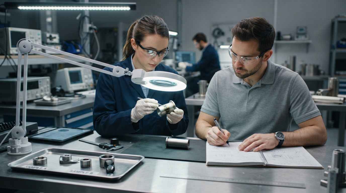
Destructive laboratory analysis sections a representative weld to examine what NDT cannot quantify: the internal structure, the depth of fusion, the hardness distribution and the chemistry of the deposited metal. You apply it to qualification coupons, to production samples drawn under a control plan and to failed parts during root-cause investigation.
Volumetric methods: radiographic and ultrasonic testing
Volumetric NDT detects defects buried inside the weld body, and it is what you use to accept full-penetration joints in pressure and structural work. Radiographic testing images density differences, so it reads porosity, slag and lack of penetration clearly, while planar defects show best when aligned with the beam. Ultrasonic testing sends sound into the joint and times the echoes, and it is highly sensitive to planar defects such as cracks and lack of fusion that radiography can miss.
Phased Array Ultrasonic Testing steers and focuses multiple beams electronically, which improves coverage and defect sizing on thick sections and complex geometries, and it increasingly replaces radiography where access or radiation safety is a constraint. Choosing between the volumetric methods is a defect-orientation decision: radiography for volumetric imperfections, ultrasonics for planar ones, and often both when the joint is critical.
Metallographic and hardness examination of the joint
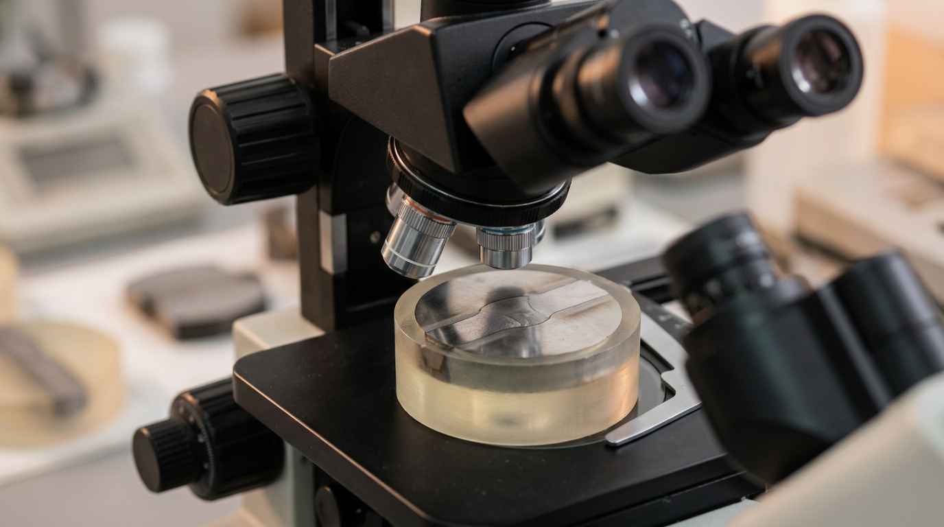
Metallographic examination cuts, mounts, polishes and etches a weld cross-section so you can measure penetration, fusion, pass sequence and the size of the heat-affected zone under the microscope. Macroscopic and microscopic examination of welds is carried out to ISO 17639, which is the reference for assessing weld structure on prepared sections, and it confirms directly whether lack of fusion or root defects are present rather than inferring them from a signal. This is the same discipline described in metallographic testing of welds and, in more general terms, in the sibling article on what a metallographic test reveals about a material.
Hardness testing across the joint maps the hardness profile from base metal through the heat-affected zone to the weld. A hard, brittle heat-affected zone is the fingerprint of an uncontrolled thermal cycle and the precondition for hydrogen cracking, so the hardness traverse tells you whether the procedure kept the metallurgy inside safe limits. Where the deposited metal is in question, alloy composition analysis confirms that the filler metal actually used matches the grade the procedure called for, a check that closes many disputes over mismatched or substituted consumables.
Non-destructive and destructive methods answer different questions. NDT tells you whether a specific part is acceptable; laboratory sectioning, hardness mapping and composition analysis tell you why a joint behaves as it does and whether the procedure behind it is sound.
Acceptance criteria: quality levels and procedure qualification
Acceptance criteria define the size and quantity of each imperfection a joint may contain and still be fit for its function, and for steel the reference is ISO 5817. That standard sets three quality levels, B (stringent), C (intermediate) and D (moderate), and you assign a level to each weld according to how critical the component is, not to how easy it is to achieve.
Quality levels under ISO 5817 tied to component criticality
A quality level is the acceptance threshold you apply to a weld, and matching it to consequence of failure is the decision that keeps inspection proportionate. Level B is where a fatigue-loaded or pressure-retaining joint in automotive, energy or capital-goods equipment belongs, because a discontinuity there can propagate under cyclic load. Level D can be appropriate for a lightly loaded, non-critical bracket where the same imperfection carries no structural consequence.
The table below summarises how the three most consequential defect families are caused, detected, judged and what they risk if they reach series production. Use it to decide which method belongs in your inspection plan for each joint.
| Defect | Typical cause | How it is detected (NDT + lab) | Acceptance criterion / standard | Risk if it reaches series |
|---|---|---|---|---|
| Porosity | Loss of gas shielding, damp or contaminated consumables, oil or rust on the joint | Radiography; surface pores by visual and penetrant; confirmed on cross-section (ISO 17639) | Size and clustering limits per quality level B/C/D (ISO 5817) | Reduced load-bearing section and leak paths in pressure or sealed joints |
| Lack of fusion / penetration | Insufficient heat input, excessive travel speed, poor joint preparation or fit-up | Ultrasonic / Phased Array; root defects on radiography; direct measurement on macro/micro section (ISO 17639) | Generally not permitted at level B; limited at C/D per ISO 5817 | Effective throat below design; fatigue initiation under cyclic load |
| Cracks | Solidification (hot) or hydrogen and restraint in a hard heat-affected zone (cold / delayed) | Surface cracks by penetrant or magnetic particle; buried cracks by ultrasonic; microstructure and hardness by ISO 17639 | Not permitted at any quality level (ISO 5817) | Progressive fracture; catastrophic failure of the assembly in service |
If your production welds are being rejected and you need an independent reading of which defect you are facing and why, send a representative sample or the disputed part for sectioning and NDT correlation, and get a report that ties each finding to its process cause.
Procedure qualification
Procedure qualification proves that a defined welding procedure produces joints meeting the required properties before it is used in production. A qualified Welding Procedure Specification (WPS) fixes the variables that govern defect formation: material grade, joint design, preheat and interpass temperature, heat input, consumable and shielding.
When defects appear despite a WPS, the gap is usually between the qualified procedure and what happens at the torch, so verifying that the deposited metal, hardness and structure of a production weld still match the qualification record is a direct check on process drift. This is where sectioning a current production coupon and comparing it against the qualification data exposes a change in consumable, a drift in parameters or a preparation that no longer matches the drawing.
How to keep welding defects out of series production
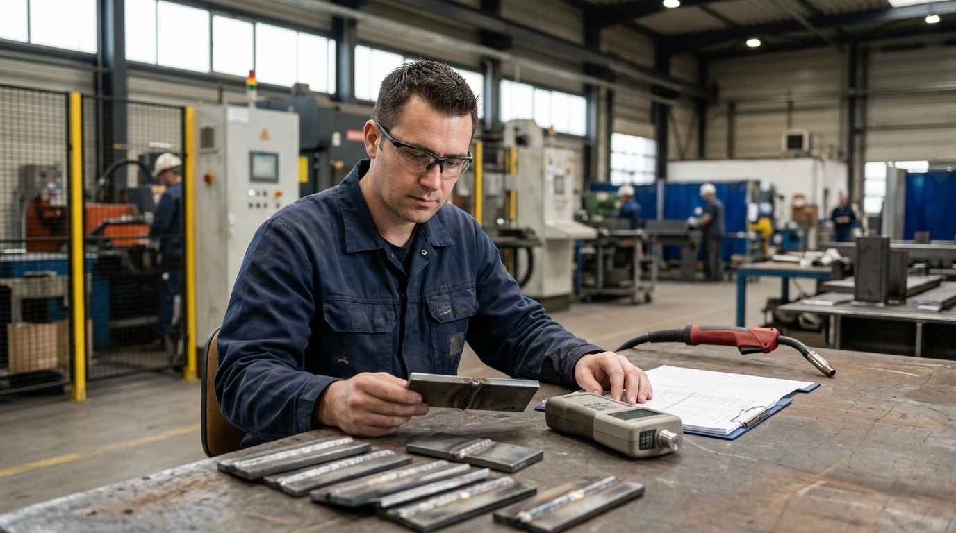
Keeping welding defects out of series production means catching the process drift that creates them before it reaches volume, through a control plan that defines what is inspected, how often and against which criteria. Inspection that only reacts to finished parts sorts good from bad; a control plan built around the defect causes prevents the bad ones from being made.
Control plan, sampling and pre-production validation
A control plan for welding assigns an inspection method and frequency to each joint according to its quality level, combining full inspection of critical welds with sampling of the rest. Pre-production validation, welding and testing representative joints under production conditions before the run starts, confirms that the qualified procedure survives contact with real fixtures, real fit-up and real operators. Sampling then monitors stability over the run, so a shift in porosity or penetration is caught as a trend rather than discovered in a customer return.
For a supplier change, a new consumable batch or a revised joint design, a small set of pre-production welds examined by NDT and cross-section gives you the evidence to release the change or hold it, without waiting for field data. Automotive and capital-goods programmes rely on exactly this step to keep a launch from carrying a latent weld problem into volume.
Correlating defects with their root cause
Root-cause correlation links each recurring defect to the specific process variable that produces it, so the corrective action targets the cause and not the symptom. A hardness spike in the heat-affected zone plus delayed cracking points to preheat and hydrogen control; recurring porosity points to shielding, consumable condition or joint cleanliness; systematic lack of penetration points to fit-up, bevel geometry or heat input.
This is the same failure-analysis logic used across broken metal components, whether the origin is a weld or the parent material. The investigation of fractures in metal parts of an industrial assembly shows how sectioning and metallurgical examination separate a welding cause from a material or design one, and the root-cause analysis of a fractured hinge shows the same reasoning applied to a load-bearing joint. The broader approach to failure analysis of automotive components ties these techniques together for series parts.
A defect found on the shop floor is a cost; a defect understood in the laboratory is a corrective action. The difference between the two is whether the finding is tied to a process variable you can control on the next weld.
Turning weld inspection into defect prevention
Controlling welding defects is less about tighter inspection at the end of the line and more about reading each joint correctly and tracing every recurring imperfection back to the variable that caused it. Non-destructive testing tells you whether a part is acceptable against ISO 5817; sectioning, hardness mapping and metallographic examination to ISO 17639 tell you why the joint behaves as it does and whether the qualified procedure is still under control. Pairing the two, and correlating the findings with WPS qualification and the process, is what keeps a latent weld problem from travelling into series production.
If you are seeing rejected welds, a disputed batch or a field failure you suspect started at a joint, send the failed part or a representative production coupon together with the WPS and the drawing, and you receive a report that identifies the defect, ties it to its process cause and states whether the joint meets its required quality level.
Frequently asked questions about welding defects
What are the most common welding defects?
The most common welding defects are porosity, lack of fusion and lack of penetration, cracks (hot and cold), slag inclusions and undercut, all classified by type under ISO 6520-1. Porosity and lack of fusion tend to be the most frequent process-driven imperfections, while cracks are the most severe because they are never accepted at any quality level. Which ones dominate on a given job depends on the process, the material and the joint, so identifying the specific defect is the starting point for correcting it.
How is porosity detected in a weld?
Porosity is detected volumetrically by radiographic testing, which images the rounded gas cavities as density differences inside the weld. Surface-breaking pores also show under visual inspection and penetrant testing. When you need to confirm the size, distribution and depth of the porosity, a metallographic cross-section examined to ISO 17639 measures it directly on the sectioned joint.
Which standard defines weld acceptance criteria?
For fusion-welded steel, ISO 5817 defines the acceptance criteria through three quality levels, B, C and D, that set the permissible size and quantity of each imperfection. You assign the quality level according to how critical the joint is: level B for fatigue-loaded or pressure-retaining welds, level D for lightly loaded non-critical ones. The defect types themselves are named and classified separately under ISO 6520-1, which the acceptance limits then reference.
Can welding defects be found without destroying the part?
Yes, non-destructive testing finds most welding defects without damaging the part, and it is the standard way to inspect production and in-service welds. Surface methods catch surface-breaking defects, while radiography and ultrasonics or Phased Array find buried ones. What NDT cannot give you is the internal microstructure, hardness distribution or filler composition, which is why destructive laboratory analysis complements it when you need to understand why a defect formed.
When is a laboratory analysis of the weld worthwhile?
A laboratory analysis is worthwhile when you need to know why a weld is failing or drifting, not just whether a single part passes. Sectioning for macro and micro examination (ISO 17639), a hardness traverse across the joint and composition analysis of the filler metal resolve disputed batches, validate a supplier or procedure change, and tie recurring defects to a controllable process variable. Send a representative production coupon or the failed part when NDT alone cannot explain the pattern.